
TM 55-2815-574-24
0054
REMOVAL
1.
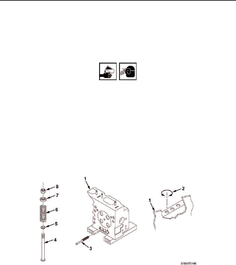
Remove push rod (Figure 1, Item 3) assembly from cylinder head (Figure 1, Item 1).
2.
Remove retaining ring (Figure 1, Item 2) from cylinder head (Figure 1, Item 1) and discard.
3.
Remove hex nut (Figure 1, Item 8), retainer (Figure 1, Item 7), spring (Figure 1, Item 6), and spring seat
(Figure 1, Item 5) from push rod (Figure 1, Item 4).
WARNING
Fuel/Oil may cause irritation to eyes or skin. Wear protective goggles, gloves, and clothing.
Failure to comply may result in personnel injury or death.
4.
Using cleaning cloth and clean lubricating oil, remove debris from spring (Figure 1, Item 6), hex nut
(Figure 1, Item 8), retainer (Figure 1, Item 7), spring (Figure 1, Item 6), spring seat (Figure 1, Item 5), and
push rod (Figure 1, Item 4).
5.
Using cleaning cloth, dry spring (Figure 1, Item 6), hex nut (Figure 1, Item 8), retainer (Figure 1, Item 7),
spring (Figure 1, Item 6), spring seat (Figure 1, Item 5), and push rod (Figure 1, Item 4).
6.
Inspect spring (Figure 1, Item 6), hex nut (Figure 1, Item 8), retainer (Figure 1, Item 7), spring
(Figure 1, Item 6), spring seat (Figure 1, Item 5), and push rod (Figure 1, Item 4) for wear or damage.
Discard defective part.
7.
Using spring tester, compress spring (Figure 1, Item 6) to a length of 2.1406 in. (5.4371 cm).
8.
Using spring tester, verify minimum load of 250 lb (113.398 kg). Discard defective part.
9.
Dispose of contaminated cleaning cloths in accordance with local procedures.
Figure 1. Cylinder Head Push Rod.
END OF TASK