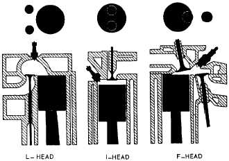
Figure 12-8.-L-, I-, and F-valve arrangement.
I-Head
Engines using the I-head construction are called
valve-in-head or overhead valve engines, because the
valves mount in a cylinder head above the cylinder. This
arrangement requires a tappet, a push rod, and a rocker
arm above the cylinder to reverse the direction of the
valve movement. Only one camshaft is required for both
valves. Some overhead valve engines make use of an
overhead camshaft. This arrangement eliminates the
long linkage between the camshaft and the valve.
F-Head
In the F-head engine, the intake valves normally are
located in the head, while the exhaust valves are located
in the engine block. This arrangement combines, in
effect, the L-head and the I-head valve arrangements.
The valves in the head are actuated from the camshaft
through tappets, push rods, and rocker arms (I-head
arrangement), while the valves in the block are actuated
directly from the camshaft by tappets (L-head
arrangement).
ENGINE CONSTRUCTION
Basic engine construction varies little, regardless of
the size and design of the engine. The intended use of
an engine must be considered before the design and size
can be determined. The temperature at which an engine
will operate has a great deal to do with the metals used
in its construction.
The problem of obtaining
service parts in the field
categorization of engines
servicing procedures and
are simplified by the
into families based on
construction and design. Because many kinds of engines
are needed for many different jobs, engines are designed
to have closely related cylinder sizes, valve
arrangements, and so forth. As an example, the General
Motors series 71 engines may have two, three, four, or
six cylinders. However, they are designed so that the
same pistons, connecting rods, bearings, valves and
valve operating mechanisms can be used in all four
engines.
Engine construction, in this chapter, will be broken
down into two categories: stationary parts and moving
parts.
STATIONARY PARTS
The stationary parts of an engine include the
cylinder block, cylinders, cylinder head or heads,
crankcase, and the exhaust and intake manifolds. These
parts furnish the framework of the engine. All movable
parts are attached to or fitted into this framework.
Engine Cylinder Block
The engine cylinder block is the basic frame of a
liquid-cooled engine, whether it is the in-line,
horizontally opposed, or V-type. The cylinder block and
crankcase are often cast in one piece that is the heaviest
single piece of metal in the engine. (See fig. 12-9.) In
small engines, where weight is an important
consideration, the crankcase may be cast separately. In
most large diesel engines, such as those used in power
plants, the crankcase is cast separately and is attached to
a heavy stationary engine base.
In practically all automotive and construction
equipment, the cylinder block and crankcase are cast in
one piece. In this course we are concerned primarily
with liquid-cooled engines of this type.
The cylinders of a liquid-cooled engine are
surrounded by jackets through which the cooling liquid
circulates. These jackets are cast integrally with the
cylinder block. Communicating passages permit the
coolant to circulate around the cylinders and through the
head.
The air-cooled engine cylinder differs from that of
a liquid-cooled engine in that the cylinders are made
individually, rather than cast in block. The cylinders of
air-cooled engines have closely spaced fins surrounding
the barrel; these fins provide an increased surface area
from which heat can be dissipated. This engine design
is in contrast to that of the liquid-cooled engine, which
has a water jacket around its cylinders.
12-9