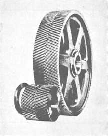
Figure 6-4.—Herringbone gear.
Figure 6-3, views B, C, and D, also shows you
three other gear arrangements in common use.
The internal gear in figure 6-3, view B, has teeth
on the inside of a ring, pointing inward toward the
axis of rotation. An internal gear is meshed with an
external gear, or pinion, whose center is offset from
the center of the internal gear. Either the internal or
pinion gear can be the driver gear, and the gear ratio
is calculated the same as for other gears—by counting
teeth.
You only need a portion of a gear where the
motion of the pinion is limited. You use the sector
gear shown in figure 6-3, view C, to save space and
material. The rack and pinion in figure 6-3, view D,
are both spur gears. The rack is a piece cut from a
gear with an extremely large radius. The rack-and-
pinion arrangement is useful in changing rotary
motion into linear motion.
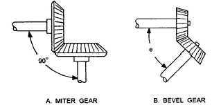
Figure 6-5.-Bevel gears.
THE BEVEL GEAR
So far most of the gears you’ve learned about
transmit motion between parallel shafts. However,
when shafts are not parallel (at an angle), we use
another type of gear called the bevel gear. This type
of gear can connect shafts lying at any given angle
because you can bevel them to suit the angle.
Figure 6-5, view A, shows a special case of the
bevel gear-the miter gear. You use the miter gears to
connect shafts having a 90-degree angle; that means
the gear faces are beveled at a 45-degree angle.
You can see in figure 6-5, view B, how bevel
gears are designed to join shafts at any angle. Gears
cut at any angle other than 45 degrees are bevel
gears.
The gears shown in figure 6-5 are straight bevel
gears, because the whole width of each tooth comes in
contact with the mating tooth at the same time.
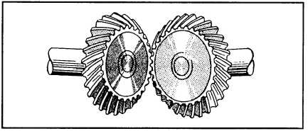
However, you’ll run across spiral bevel gears with
teeth cut to have advanced and trailing ends. Figure
6-6 shows you what spiral bevel gears look like. They
have the same advantage as other spiral (helical)
gears—less lost motion and smoother, quieter
operation.
Figure 6-6.-Spiral bevel gears.
6-3