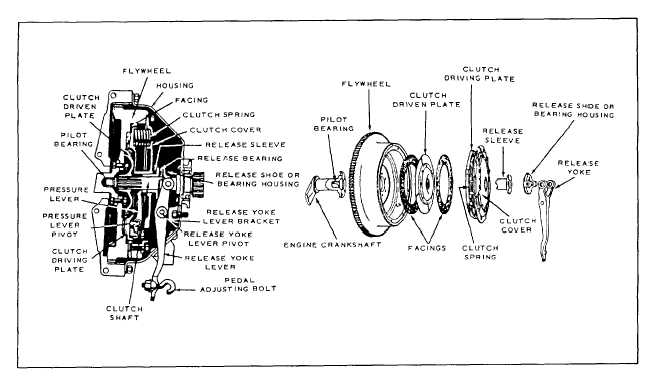
Figure 13-2.-Exploded and cross-sectional views of a plate clutch.
or power takeoff units. These units may be used to
(disc). The driver of the automobile controls the
operate accessory attachments. The propeller shafts and
clutch assemblies of these power trains are very much
like those used to drive the wheels.
THE CLUTCH
The clutch is placed in the power train of motorized
equipment for two purposes:
First, it provides a means of disconnecting the
power of the engine from the driving wheels and
accessory equipment. When you disengage the clutch,
the engine can run without driving the vehicle or
operating the accessories.
Second, when you start the vehicle, the clutch
allows the engine to take up the load of driving the
vehicle or accessories gradually and without shock.
Clutches are located in the power train between the
source of power and the operating unit. Usually, they are
placed between the engine and the transmission
assembly, as shown in figure 13-1.
Clutches generally transmit power from the
clutch-driving member to the driven member by
friction. Strong springs within the plate clutch (fig. 13-2)
gradually bring the driving member (plate), secured to
the engine flywheel, in contact with the driven member
pressure of the springs through use of the clutch. If the
driver only applies light pressure, little friction takes
place between the two members, which permits the
clutch to slip. As the driver increases pressure, friction
also increases and less slippage occurs. When the
driver’s foot releases pressure from the clutch pedal and
applies full spring pressure, the driving plate and driven
disc move at the same speed. All slipping then stops
because of the direct connection between the driving
and driven shafts.
In most clutches, a direct mechanical linkage exists
between the clutch pedal and the clutch release yoke
lever. Many late model vehicles and some larger units
that require greater pressure to release the spring use a
hydraulic clutch release system. A master cylinder (fig.
13-3), similar to the brake master cylinder, attaches to
the clutch pedal. A cylinder, similar to a single-acting
brake wheel cylinder, connects to the master cylinder by
flexible pressure hose or metal tubing (fig. 13-3). The
slave cylinder connects to the clutch release yoke lever.
Movement of the clutch pedal actuates the clutch master
cylinder. Hydraulic pressure transfers this movement to
the slave cylinder, which, in turn, actuates the clutch
release yoke lever.
We use various types of clutches. Most passenger
cars and light trucks use the previously mentioned plate
13-2