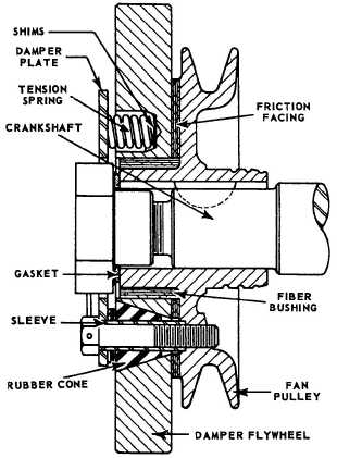
Figure 12-21.-Sectional view of a typical
vibration damper.
Engine Flywheel
The flywheel mounts at the rear of the crankshaft
near the rear main bearing. This is usually the longest
and heaviest main bearing in the engine, as it must
support the weight of the flywheel.
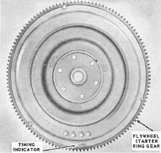
The flywheel (fig. 12-22) stores up rotation energy
during the power impulses of the engine. It releases
this energy between power impulses, thus assuring
less fluctuation in engine speed and smoother engine
operation. The size of the flywheel will vary with the
number of cylinders and the general construction of
the engine. With the large number of cylinders and the
consequent overlapping of power impulses, there is less
need for a flywheel; consequently, the flywheel can be
relatively small. The flywheel rim carries a ring gear,
either integral with or shrunk on the flywheel, that
meshes with the starter driving gear for cranking the
engine. The rear face of the flywheel is usually
machined and ground and acts as one of the pressure
surfaces for the clutch, becoming a part of the clutch
assembly.
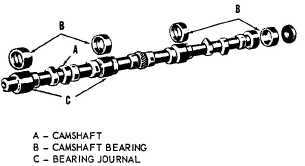
Figure 12-23.-Camshaft and bushings.
Valves and Valve Mechanisms
Most engines have two valves for each cylinder, one
intake and one exhaust valve. Since each of these
valves operates at different times, separate operating
mechanisms must be provided for each valve. Valves
are normally held closed by heavy springs and by
compression in the combustion chamber. The purpose
of the valve-actuating mechanism is to overcome the
spring pressure and open the valves at the proper time.
The valve-actuating mechanism includes the engine
camshaft, camshaft followers (tappets), pushrods, and
rocker arms.
CAMSHAFT.—The camshaft (fig. 12-23) is enclosed in
the engine block. It has eccentric lobes (cams) ground
on it for each valve in the engine. As the
12-19