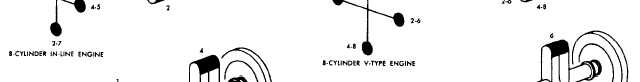
Figure 12-20.-Crankshaft and throw arrangements commonly used.bearing surfaces for the connecting rods and the mainbearings. It is case-hardened (coated in a furnace withcopper alloyed and carbon). These bearing surfaces arecalled journals. The crankshaft counterweights impedethe centrifugal force of the connecting rod and assemblyattached to the throws or points of bearing support.These throws must be placed so that they counter-balance each other.Crankshaft and throw arrangements for four-, six-,and eight-cylinder engines are shown in figure 12-20.Four-cylinder engine crankshafts have either three orfive main support bearings and four throws in one plane.As shown in the figure, the four throws for the number1 and 4 cylinders (four-cylinder engine) are 180° fromthose for the number 2 and 3 cylinders. On six-cylinderengine crankshafts, each of the three pairs of throws isarranged 120° from the other two. Such crankshafts maybe supported by as many as seven main bearings—oneat each end of the shaft and one between each pair ofcrankshaft throws. The crankshafts of eight-cylinderV-type engines are similar to those of the four-cylinderin-line type. They may have each of the four throwsfixed at 90° from each other (as in fig. 12-20) for betterbalance and smoother operation.V-type engines usually have two connecting rodsfastened side by side on one crankshaft throw. With thisarrangement, one bank of the engine cylinders is setslightly ahead of the other to allow the two rods to cleareach other.Vibration DamperThe power impulses of an engine result in torsionalvibration in the crankshaft. A vibration damper mountedon the front of the crankshaft controls this vibration (fig.12-21). If this torsional vibration were not controlled,the crankshaft might actually break at certain speeds.Most types of vibration dampers resemble aminiature clutch. A friction facing is mounted betweenthe hub face and a small damper flywheel. The damperflywheel is mounted on the hub face with bolts that gothrough rubber cones in the flywheel. These conespermit limited circumferential movement between thecrankshaft and damper flywheel. That reduces theeffects of the torsional vibration in the crankshaft.Several other types of vibration dampers are used;however, they all operate in essentially the same way.2-18
Integrated Publishing, Inc. - A (SDVOSB) Service Disabled Veteran Owned Small Business