Chapter 3—ENGINE MAINTENANCE
danger that the piston will strike valves that may
be open and extending into the cylinder. Make
certain that any gears removed are replaced in the
original position. Special punch marks, or
numbers (figure 3-24), are usually found on gear
teeth that should mate. If they are not present,
make identifying marks to facilitate the correct
mating of the gears later.
Bearing, bushing, and gear clearances must be
properly maintained. If bushing clearances exceed
the allowable value, the bushings must be re-
newed. The allowable values for backlash and
bushing clearances should be obtained from the
instruction manual for the engine involved.
Usually, a broken or chipped gear must be
replaced. Care should be exercised in determin-
ing whether a pitted gear should be replaced.
BLOWER ROTOR GEARS
One of the most important parts of a root type
blower is the set of gears that drive and syn-
chronize the two rotors. Satisfactory operation
depends on the condition of these gears.
Worn gears are found by measuring the
backlash of the gear set. Gears with a greater
backlash than specified in the applicable technical
manual are considered to be excessively worn and,
if not replaced, will eventually cause extensive
damage to the entire blower assembly.
A certain amount of gear wear is to be
expected, but scored and otherwise damaged rotor
lobes resulting from excessively worn gears are
inexcusable. It is the duty of the engineering force
to inspect the gears and lobes, and to measure the
clearance at frequent intervals. During the inspec-
tion, it will be possible to measure accurately the
values of backlash. These values should be re-
corded. By observing the rate of increase of wear,
it will be possible to estimate the life of the gears
and to determine when it will be necessary to
replace them.
Lobe clearance can be found by determining
the difference of the maximum and minimum
rotor lobe clearance at the same distance from the
center. To find the maximum clearance, hold the
rotors so that there is maximum clearance between
the two rotor lobes. Then, with feeler gages deter-
mine the value of the rotor lobe clearance. (See
figure 3-25.)
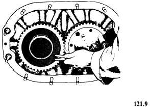
Figure 3-26.—Checking the backlash of blower rotor gears.
The minimum clearance is found in a similar
manner except that rotor lobes are held in such
a position as to take up all slack and backlash.
The difference of the two clearance readings is
the value of the backlash of the rotor lobes. Since
a change in lobe clearance is normally caused by
wear of the gears, the gear clearance must be
checked. The most direct method for checking
gear clearance is by the use of feeler gages. (See
figure 3-26.)
Any gear set which has excessive lash or shows
any sign of fracture must be replaced with a new
set. Since blower drive gears come in matched sets,
gears from different sets must not be
interchanged.
CHAIN MECHANISMS
In some engines, chains are not only used to
drive camshafts and auxiliaries but also to drive
such parts as rotating supercharger valves. Con-
necting links for two types of chains are shown
in figure 3-27. Note that the connecting pins in
one are secured by cotter pins, while the joint pins
shown in the other are riveted.
The principal causes of drive chain failure are
improper chain tension, lack of lubrication,
sheared cotter pins or improperly riveted joint
pins, and misalignment of parts, especially idler
gears.
Chain drives should be checked for any symp-
toms of such difficulties, in accordance with the
instructions in the appropriate engine manual. The
tension should be adjusted as required during
3-39


