needle valve even though it has previously been
done at the factory or repair facility. This adjust-
ment must be made with the governor installed
and controlling an engine with a load. If this is
not done, high overspeeds and low underspeeds
after load changes will result and the return to
normal speeds will be slowed. Maintenance and
repair of each unit must be in accordance with
the manufacturer’s maintenance manual and the
PMS.
NOTE: When governor troubles are
suspected, before performing any maintenance or
adjustments, always disconnect the governor fuel
rod end from the fuel control rack and ensure that
there is no sticking or binding of the rack. This
procedure is necessary to determine if the trou-
ble is actually in the governor.
The chart in table 3-1 lists some of the
probable causes of trouble which are common to
most hydraulic governors. This chart should be
used for training purposes only; it must NOT be
used to troubleshoot a governor. Always use the
applicable manufacturer’s instruction manual for
troubleshooting. Following are the definitions of
the terms used in the chart.
HUNT: A rhythmic variation of speed which
can be eliminated by blocking the fuel linkage
manually, but which will reappear when returned
to governor control.
SURGE: A rhythmic variation of speed always
of large magnitude which can be eliminated by
blocking the fuel linkage and which will not reap-
pear when returned to governor control unless the
speed adjustment of the load changes.
JIGGLE: A high frequency vibration of the
governor fuel rod end or engine linkage. Do not
confuse jiggle with normal regulating action of
the governor.
Mechanical Governors
Mechanical governors used in the Navy are
generally of the spring-loaded flyball type. All
mechanical governors have a speed droop. This
means that as the load is increased at a constant
throttle setting, the speed of the engine will drop
or droop slightly, rather than remain constant.
Consequently, mechanical governors are never
used where absolute constant speeds are necessary.
There are several types of mechanical gover-
nors. Two of the most common types are used
on GM 71 engines. One type, known as the
constant-speed governor, is used on generator sets
and is designed to hold the speed of the engine
at a predetermined operating speed. The other
type is similar in construction and is used primar-
ily for propulsion engines. It has a throttle plate
so designed that speeds intermediate between idl-
ing and full speeds may be obtained by manual
adjustment. The following description applies to
both types of governors. Do note, however, that
on the constant-speed governor, there is no buf-
fer spring adjustment.
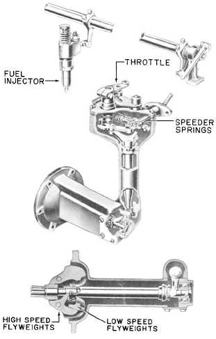
In the idling speed range, control is effected
by centrifugal force of two sets of flyweights
(figure 3-15), large and small, acting against a light
Chapter 3—ENGINE MAINTENANCE
121.22
Figure 3-15.—GM mechanical governor.
3-23