ENGINEMAN 1 & C
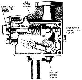
(low speed) spring. Maximum speed control is ef-
fected by the action of the high speed (small)
flyweights acting against a heavy (high speed)
spring. (See figure 3-16.)
Mechanical governor faults usually manifest
themselves in speed variations; however, not all
speed variations indicate governor faults. When
improper speed variations appear do the
following:
1. Check the load to be sure that speed
changes are not the result of load fluctuations.
2. If the load is found to be steady, check the
engine to be sure all cylinders are firing properly.
3. Make sure there is no binding in the gover-
nor mechanism or operating linkage between
governor and engine, and that no binding exists
in the injector control rack shaft or its mounting
brackets. If you find no binding anywhere and
the governor still fails to control the engine prop-
erly, you may assume the governor is worn or
unfit for further service until the unit has been
completely disassembled, inspected, and rebuilt
or replaced.
121.23
Figure 3-16.—Mechanical governor control mechanism.
Adjustment procedures for the replacement of
any governor are listed in the manufacturer’s
instruction manual and should be followed with
particular attention given to the precautions listed.
OVERSPEED SAFETY DEVICES
Mechanical overspeed trips depend on the cen-
trifugal forces developed by the engine and should
be maintained in good working condition. A
faulty overspeed device can endanger not only the
engine but also personnel if the engine explodes
or flies apart because of uncontrolled speed.
The engine instruction manual contains infor-
mation as to the speed at which the overspeed is
supposed to function. Most overspeed trips are
adjustable. Prior to making any change in the ad-
justment of the overspeed trip, determine if the
engine did not trip out for some reason other than
the action of the element of the overspeed trip.
It is highly advisable that you first check the ac-
curacy of the tachometer and then test the
overspeed trip. All spring tension adjustments and
linkage adjustments to an overspeed trip are
critical. Instructions given for making these ad-
justments are found in the manufacturer’s instruc-
tions manual and must be followed.
Hydraulic overspeed trips are extremely sen-
sitive to dirt. Dirt or lacquer-like deposits may
cause a trip to bind internally. The speed sensitive
element must be kept clean and so should all parts
of the linkage and mechanisms incorporated in
this speed sensitive element. When painting
around the engine, the painter should be cau-
tioned against allowing paint to fall on joints,
springs, pins, and other critical points in the
linkage.
All linkage binding should be eliminated. If
parts are bent, badly worn, improperly installed,
dirty, or if their motion is restricted by some other
part of the engine, the trip will not function
properly. On occasion the drive shaft of the
overspeed trip may be broken and prevent rota-
tion of the flyweight and the overspeed trip.
Insufficient oil in the hydraulic trip may be
another source of this problem. Oil should be
maintained at the level specified in the instruc-
tion manual.
The cause of any malfunction should be deter-
mined and eliminated. This will involve cleaning
the trip and its linkage, removing the source of
3-24