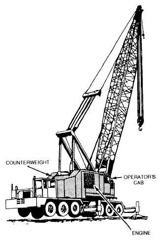
Figure 12-20.—House assembly.
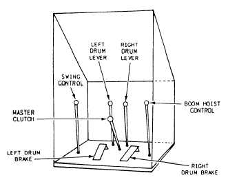
Figure 12-21.—Lattice boom crane control levers.
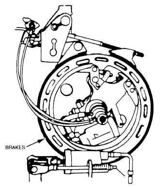
2. The left drum brake pedal is used to hold and
lower loads placed on the hoist line. When locked, it
prevents the hook block and wire rope from unwinding
on the hoist drum. Figure 12-22 shows a typical hoist
brake assembly.
Figure 12-22.—Hoist brake assembly.
3. The main drum lever engages power to raise and,
on some models, support lowering of loads placed on
the main hoist drum.
4. The master clutch engages the power from the
power source to the hoist and swing mechanisms.
5. The secondary drum lever engages power to
raise and, on some models, support lowering of loads
placed on the secondary hoist drum.
6. The right drum brake pedal is used to hold and
lower loads placed on the hoist line. When locked, it
prevents the hook block and wire rope from unwinding
on the hoist drum.
7. The boom hoist lever allows for the raising and
lowering of the boom.
HOISTING MECHANISM.— The hoisting
mechanism provides the mechanical power to lift and
lower loads. The hoisting mechanism usually has two
hoist drums that are mounted side by side on one shaft
or in tandem. A separate clutch and brake controls each
hoist. The control levers, operating the clutches and
brakes, are normally power-assisted with hydraulics or
air pressure. A lifting operation requires the use of one
drum; whereas the clamshell, dragline, and pile-driving
operations require the use of two.
ENGINE.— The engine provides power to the
hoisting mechanism through a gearbox or, in some
12-11