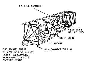
33Figure 12-12.-Lattice boom terminology.
removed from service. When the main cords of tubular
boom sections are damaged in any manner, including
slight dents, they are severely weakened and have failed
at loads significantly below capacities. As outlined in
the 11200.1, structural repairs will not be made without
written approval from COMSECOND/COM-
THIRDNCB equipo offices.
In the NCF, sections normally come in 10- to
20-foot lengths.
When adding several sections of
different lengths, check the operator’s manual for boom
section configuration. If this information is not in the
operator’s manual, a rule of thumb used when mixing
short boom sections with long sections, you install the
shorter sections closest to the boom butt; for example,
if you use two 10-foot sections and one 20-foot section,
install the two 10-foot sections closest to the boom butt.
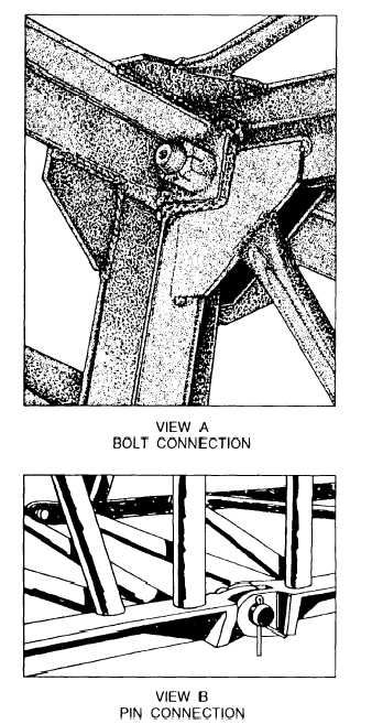
The boom sections are bolted by plate (flange)
connections (fig. 12-13, view A) or pin and clevis
connections (fig. 12-13, view B). The most common is
the pin and clevis.
All boom sections that come with a crane will have
an attachment identification number attached that
assigns the boom section to a specific crane.
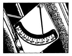
Boom Angle Indicators
Boom angle indicators are normally mounted on the
boom butt, visually readable by the operator. On most
models in the NCF, the boom angle indicator is a metal
plate with degree numbers (0 to 90 degrees) and a freely
swinging arm that reacts as the boom angle changes (fig.
12-14). The numbers and arm should remain clean and
visually readable at all time.
The capacities that are listed on the crane load charts
are also based on and vary with the boom angle of the
crane. On hydraulic cranes, the boom angle is the angle
between the bottom of the boom butt and the horizontal
Figure 12-13.—Boom sections connection.
Figure 12-14.—Boom angle indicator.
12-7