charge of air or an inert gas such as nitrogen.
Sometimes the amount of air charge is limited to
the volume within the accumulator; other
installations may use separate air flasks which are
piped to the air side of the accumulator. Piston
accumulators may be mounted in any position.
The gas portion of the accumulator may be
located on either side of the piston. For example,
in submarine hydraulic systems with tailrod
pistons, the gas is usually on the bottom and the
fluid on top; in surface ships with floating pistons,
the gas is usually on the top. The orientation of
the accumulator and the type of accumulator are
based upon such criteria as available space,
maintenance accessibility, size, need for external
monitoring of the piston’s location (tailrod
indication), contamination tolerance, seal life, and
safety. The purpose of the piston seals is to keep
the fluid and the gas separate.
Usually, tailrod accumulators use two piston
seals, one for the air side and one for the oil side,
with the space between them vented to the
atmosphere through a hole drilled the length of
the tailrod. When the piston seals fail in this type
of accumulator, air or oil leakage is apparent.
However, seal failure in floating piston or
nonvented tailrod accumulators will not be as
obvious. Therefore, more frequent attention to
venting or draining the air side is necessary. An
indication of worn and leaking seals can be
detected by the presence of significant amounts
of oil in the air side.
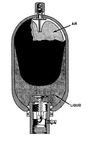
BLADDER-TYPE ACCUMULATORS
Bladder- or bag-type accumulators consist of
a shell or case with a flexible bladder inside the
shell. See figure 9-7. The bladder is larger in
diameter at the top (near the air valve) and
gradually tapers to a smaller diameter at the
bottom. The synthetic rubber is thinner at the top
of the bladder than at the bottom. The operation
of the accumulator is based on Barlow’s formula
for hoop stress, which states: “The stress in a
circle is directly proportional to its diameter and
wall thickness.” This means that for a certain
thickness, a large diameter circle will stretch faster
than a small diameter circle; or for a certain
diameter, a thin wall hoop will stretch faster than
a thick wall hoop. Thus, the bladder will stretch
around the top at its largest diameter and thinnest
wall thickness, and then will gradually stretch
downward and push itself outward against the
walls of the shell. As a result, the bladder is
capable of squeezing out all the liquid from.
Figure 9-7.—Bladder-type accumulator.
the accumulator. Consequently, the bladder
accumulator has a very high volumetric efficiency.
In other words, this type of accumulator is
capable of supplying a large percentage of the
stored fluid to do work.
The bladder is precharged with air or inert gas
to a specified pressure. Fluid is then forced into
the area around the bladder, further compressing
the gas in the bladder. This type of accumulator
has the advantage that as long as the bladder is
intact there is no exposure of fluid to the gas
charge and therefore less danger of an explosion.
DIRECT-CONTACT GAS-TO-FLUID
ACCUMULATORS
Direct-contact gas-to-fluid accumulators
generally are used in very large installations where
it would be very expensive to require a piston-
or bladder-type accumulator. This type of
accumulator consists of a fully enclosed cylinder,
mounted in a vertical position, containing a liquid
9-6