As the load is lifted and begins to dump, the
required force becomes less and less until the load
is completely dumped. During the raise cycle,
pressurized fluid enters the cylinder through port
A (fig. 10-3) and acts on the bottom surface of
all three rams. Ram 1 has a larger surface area
and, therefore, provides the greater force for the
initial load, As ram 1 reaches the end of its stroke
and the required force is decreased, ram 2 moves,
providing the smaller force needed to continue
raising the load. When ram 2 completes its stroke,
a still smaller force is required. Ram 3 then moves
outward to finish raising and dumping the load.
Some telescoping ram-type cylinders are of the
single-acting type. Like the single-acting ram
discussed previously, these telescoping ram-type
cylinders are retracted by gravity or mechanical
force. Some hydraulic jacks are equipped with
telescoping rams. Such jacks are used to lift
vehicles with low clearances to the required height.
Other types of telescoping cylinders, like the
one illustrated in figure 10-3, are of the double-
acting type. In this type, fluid pressure is used for
both the extension and retraction strokes. A four-
way directional control valve is commonly used
to control the operation of the double-acting type.
Note the small passages in the walls of rams 1 and
2. They provide a path for fluid to flow to and
from the chambers above the lips of rams 2 and
3. During the extension stroke, return fluid flows
through these passages and out of the cylinder
through port B. It then flows through the
directional control valve to the return line or
reservoir.
To retract the rams, fluid under pressure is
directed into the cylinder through port B and acts
against the top surface areas of all three ram lips.
This forces the rams to the retracted position. The
displaced fluid from the opposite side of the rams
flows out of the cylinder through port A, through
the directional control valve to the return line or
reservoir.
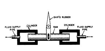
Dual Rams
A dual ram assembly consists of a single ram
with a cylinder at either end (fig. 10-4). Fluid can
be directed to either cylinder, forcing the ram to
move in the opposite direction. The ram is
connected through mechanical linkage to the unit
to be operated. A four-way directional control
valve is commonly used to operate the dual ram.
When the control valve is positioned to direct fluid
under pressure to one of the cylinders (let’s say
the left one), the ram is forced to the right. This
Figure 10-4.-Dual ram actuating assembly.
action displaces the fluid in the opposite cylinder.
The displaced fluid flows back through the
directional control valve to the return line or
reservoir in hydraulic systems or to the
atmosphere in pneumatic systems.
Dual ram actuating assemblies are used in
steering systems of most ships. In some systems,
one assembly is used to actuate the rudder in either
direction; while in other systems, two assemblies
are used for the same purpose.
PISTON-TYPE CYLINDERS
An actuating cylinder in which the cross-
sectional area of the piston is less than one-half
the cross-sectional area of the movable element
is referred to as a piston-type cylinder. This type
of cylinder is normally used for applications that
require both push and pull functions. The piston-
type cylinder is the most common type used in
fluid power systems.
The essential parts of a piston-type cylinder
are a cylindrical barrel, a piston and rod, end caps,
and suitable seals. The end caps are attached to
the ends of the barrel. These end caps usually
contain the fluid ports. The end cap on the rod
end contains a hole for the piston rod to pass
through. Suitable seals are used between the hole
and the piston rod to keep fluid from leaking out
and to keep dirt and other contaminants from
entering the barrel. The opposite end cap of most
cylinders is provided with a fitting for securing
the actuating cylinder to some structure. This end
cap is referred to as the anchor end cap.
The piston rod may extend through either or
both ends of the cylinder. The extended end of
the rod is normally threaded so that some type
of mechanical connector, such as an eyebolt or
a clevis, and a locknut can be attached. This
threaded connection of the rod and mechanical
connector provides for adjustment between the
rod and the unit to be actuated. After the correct
10-3