adjustment is made, the locknut is tightened
against the connector to prevent the connector
from turning. The other end of the connector is
attached, either directly or through additional
mechanical linkage, to the unit to be actuated.
In order to satisfy the many requirements of
fluid power systems, piston-type cylinders are
available in various designs.
Single-Acting Cylinder
The single-acting piston-type cylinder is similar
in design and operation to the single-acting
ram-type cylinder. The single-acting piston-type
cylinder uses fluid pressure to provide the force
in one direction, and spring tension, gravity,
compressed air, or nitrogen is used to provide the
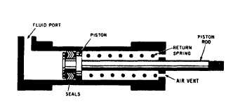
force in the opposite direction. Figure 10-5 shows
a single-acting,
spring-loaded, piston-type
actuating cylinder. In this cylinder the spring is
located on the rod side of the piston. In some
spring-loaded cylinders the spring is located on
the blank side, and the fluid port is on the rod
side of the cylinder.
A three-way directional control valve is
normally used to control the operation of the
single-acting piston-type cylinder. To extend the
piston rod, fluid under pressure is directed
through the port into the cylinder (fig. 10-5). This
pressure acts on the surface area of the blank side
of the piston and forces the piston to the right.
This action moves the rod to the right, through
the end of the cylinder, thus moving the actuated
unit in one direction. During this action, the
spring is compressed between the rod side of the
piston and the end of the cylinder. The length of
the stroke depends upon the physical limits within
the cylinder and the required movement of the
actuated unit.
To retract the piston rod, the directional
control valve is moved to the opposite working
position, which releases the pressure in the
Figure 10-5.—Single-acting, spring-loaded, piston-type
actuating cylinder.
cylinder. The spring tension forces the piston to
the left, retracting the piston rod and moving the
actuated unit in the opposite direction. The fluid
is free to flow from the cylinder through the port,
back through the control valve to the return line
in hydraulic systems or to the atmosphere in
pneumatic systems.
The end of the cylinder opposite the fluid port
is vented to the atmosphere. This prevents air
from being trapped in this area. Any trapped air
would compress during the extension stroke,
creating excess pressure on the rod side of the
piston. This would cause sluggish movement of
the piston and could eventually cause a complete
lock, preventing the fluid pressure from moving
the piston.
The spring-loaded cylinder is used in arresting
gear systems on some models of carrier aircraft.
To raise (retract) the arresting hook, fluid pressure
is directed through the arresting hook control
valve to the rod side of the cylinder. This force
moves the piston, which, through the rod and
mechanical linkage, retracts the arresting hook.
The arresting hook extends when fluid pressure
is released from the rod side of the cylinder,
allowing the spring to expand.
Leakage between the cylinder wall and piston
is prevented by adequate seals. The piston in
figure 10-5 contains V-ring seals.
Double-Acting Cylinder
Most piston-type actuating cylinders are
double-acting, which means that fluid under
pressure can be applied to either side of the piston
to apply force and provide movement.
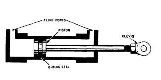
One design of the double-acting cylinder is
shown in figure 10-6. This cylinder contains one
piston and piston rod assembly. The stroke of the
piston and piston rod assembly in either direction
is produced by fluid pressure. The two fluid ports,
one near each end of the cylinder, alternate as inlet
and outlet ports, depending on the direction of
Figure 10-6.-Doub1e-acting piston-type actuating cylinder.
10-4