flow from the directional control valve. This
actuator (fig. 10-6) is referred to as an unbalanced
actuating cylinder because there is a difference in
the effective working areas on the two sides of
the piston. Therefore, this type of cylinder is
normally installed so that the blank side of the
piston carries the greater load; that is, the cylinder
carries the greater load during the piston rod
extension stroke.
A four-way directional control valve is
normally used to control the operation of this type
of cylinder. The valve can be positioned to direct
fluid under pressure to either end of the cylinder
and allow the displaced fluid to flow from the
opposite end of the cylinder through the control
valve to the return line in hydraulic systems or
to the atmosphere in pneumatic systems.
There are applications where it is necessary to
move two mechanisms at the same time. In this
case, double-acting piston-type actuating cylinders
of different designs are required. See figures 10-7
and 10-8.
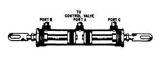
Figure 10-7 shows a three-port, double-acting
piston-type actuating cylinder. This actuator
contains two pistons and piston rod assemblies.
Fluid is directed through port A by a four-way
directional control valve and moves the pistons
outward, thus moving the mechanisms attached
to the pistons’ rods. The fluid on the rod side of
each piston is forced out of the cylinder through
ports B and C, which are connected by a common
line to the directional control valve. The displaced
fluid then flows through the control valve to the
return line or to the atmosphere.
When fluid under pressure is directed into the
cylinder through ports B and C, the two pistons
move inward, also moving the mechanisms
attached to them. Fluid between the two pistons
is free to flow from the cylinder through port A
and through the control valve to the return line
or to the atmosphere.
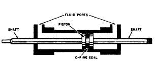
The actuating cylinder shown in figure 10-8
is a double-acting balanced type. The piston rod
extends through the piston and out through both
ends of the cylinder. One or both ends of the
Figure 10-7.—Three-port, double-acting actuating cylinder.
Figure 10-8.-Balanced, double-acting piston-type actuating
cylinder.
piston rod may be attached to a mechanism to
be operated. In either case, the cylinder provides
equal areas on each side of the piston. Therefore,
the same amount of fluid and force is used to
move the piston a certain distance in either
direction.
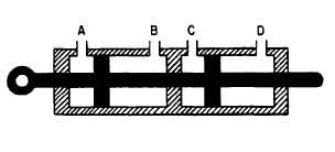
Tandem Cylinders
A tandem actuating cylinder consists of two
or more cylinders arranged one behind the other
but designed as a single unit (fig. 10-9). This type
of actuating cylinder is used in applications that
require two or more independent systems; for
example, power-operated flight control systems
in naval aircraft.
The flow of fluid to and from the two
chambers of the tandem actuating cylinder is
provided from two independent hydraulic systems
and is controlled by two sliding spool directional
control valves. In some applications, the control
valves and the actuating cylinder are two separate
units. In some units, the pistons (lands) of the two
sliding spools are machined on one common shaft.
In other applications, the valves and the actuator
are directly connected in one compact unit.
Although the two control valves are hydraulically
independent, they are interconnected mechanically.
In other units, the two sliding spools are connected
through mechanical linkages with a synchronizing
rod. In either case, the movement of the two
sliding spools is synchronized, thus equalizing the
Figure 10-9.—Tandem actuating cylinder.
10-5