Radial-Piston Motor
continues as long as fluid under pressure enters
the cylinders.
The radial-piston motor operates in reverse of
the radial-piston pump. In the radial-piston pump,
as the cylinder block rotates, the pistons press
against the rotor and are forced in and out of the
cylinders, thereby receiving fluid and pushing it
out into the system. In the radial motor, fluid is
forced into the cylinders and drives the pistons
outward. The pistons pushing against the rotor
cause the cylinder block to rotate.
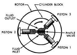
The operation of a radial-piston motor is
shown in figure 10-15. This motor is shown with
three pistons for simplicity. Normally it contains
seven or nine pistons. When liquid is forced into
the cylinder bore containing piston 1, the piston
moves outward since the liquid cannot be
compressed. This causes the cylinder to rotate in
a clockwise direction. As the force acting on
piston 1 causes the cylinder block to rotate, piston
2 starts to rotate and approach the position of
piston 3. (Note that the distance between the
cylinder block and the reaction ring of the rotor
gets progressively shorter on the top and right half
of the rotor.)
As piston 2 rotates, it is forced inward and,
in turn, forces the fluid out of the cylinder. Since
there is little or no pressure on this side of the
pintle valve, the piston is easily moved in by its
contact with the reaction ring of the rotor. The
fluid is easily forced out of the cylinder and back
to the reservoir or to the inlet side of the pump.
As the piston moves past the midpoint, or past
the shortest distance between the cylinder block
and the rotor, it enters the pressure side of the
pintle valve and fluid is forced into the cylinder.
Piston 3 then becomes the pushing piston and in
turn rotates the cylinder block. This action
Figure 10-15.—Operation of a radial-piston motor.
The direction of rotation of the motor (fig.
10-15) is changed by reversing the flow of fluid
to it. Admitting fluid under pressure on the top
side of the pintle valve forces piston 3 out of the
cylinder block. This causes the cylinder to rotate
in the counterclockwise direction.
Axial-Piston Motor
The variable-stroke axial-piston pump is often
used as a part of variable speed gear, such as
electrohydraulic anchor windlasses, cranes,
winches, and the power transmitting unit in
electrohydraulic steering engines. In those cases,
the tilting box is arranged so that it maybe tilted
in either direction. Thus it maybe used to transmit
bidirectional power hydraulically to pistons or
rams, or it may be used to drive a hydraulic
motor. In the latter use, the pump is the A-end
of the variable speed gear and the hydraulic motor
is the B-end.
The B-end of the hydraulic unit of the
hydraulic speed gear is exactly the same as the
A-end of the variable-stroke pump mentioned
previously. However, it generally does not have
a variable-stroke feature. The tilting box is
installed at a permanently fixed angle. Thus, the
B-end becomes a fixed-stroke axial-piston motor.
Figure 10-16 illustrates an axial-piston hydraulic
speed gear with the A-end and B-end as a single
unit. It is used in turrets for train and elevation
driving units. For electrohydraulic winches and
cranes, the A-end and B-end are in separate
housings connected by hydraulic piping.
Hydraulic fluid introduced under pressure to
a cylinder (B-end) tries to push the piston out of
the cylinder. In being pushed out, the piston,
through its piston rod, will seek the point of
greatest distance between the top of the cylinder
and the socket ring. The resultant pressure of the
piston against the socket ring will cause the
cylinder barrel and the socket ring to rotate. This
action occurs during the half revolution while the
piston is passing the intake port of the motor,
which is connected to the pressure port of the
pump. After the piston of the motor has taken
all the hydraulic fluid it can from the pump, the
piston passes the valve plate land and starts to
discharge oil through the outlet ports of the motor
10-10