the lobes, which unseat one pressure poppet and
one return/exhaust poppet (fig. 6-31). The valve
is now in the working position. Fluid under
pressure, entering the pressure port, flows through
the vertical fluid passages in both pressure poppets
seats. Since only one pressure poppet, IN (2), is
unseated by the cam lobe, the fluid flows past the
open poppet to the inside of the poppet seat. From
there it flows through the diagonal passages, out
one cylinder port, C2, and to the actuating unit.
Return fluid from the actuating unit enters the
other cylinder port, C1. It then flows through the
corresponding fluid passage, past the unseated
return poppet, OUT (1), through the vertical fluid
passages, and out the return/exhaust port. When
the camshaft is rotated in the opposite direction
to the neutral position, the two poppets seat and
the flow stops. When the camshaft is further
rotated in this direction until the stop pins hits,
the opposite pressure and return poppets are
unseated. This reverses the flow in the working
lines, causing the actuating unit to move in the
opposite direction.
Rotary Spool Valve
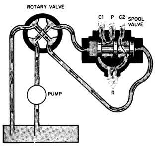
Four-way directional control valves of this
type are frequently used as pilot valves to direct
flow to and from other valves (fig. 6-32). Fluid
is directed from one source of supply through the
rotary valve to another directional control valve,
where it positions the valve to direct flow from
another source to one side of an actuating unit.
Fluid from the other end of the main valve flows
through a return line, through the rotary valve
to the return or exhaust port.
The principal parts of a rotary spool direc-
tional control valve are shown in figure 6-22.
Figure 6-31.—Working view of a poppet-type, four-way
directional control valve.
Figure 6-32.—Sliding spool valve controlled by a rotary spool
valve.
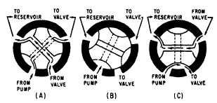
Figure 6-33 shows the operation of a rotary spool
valve. Views A and C show the valve in a position
to deliver fluid to another valve, while view B
shows the valve in the neutral position, with all
passages through the valve blocked.
Rotary spool valves can be operated manually,
electrically, or by fluid pressure.
Sliding Spool Valve
The sliding spool four-way directional control
valve is similar in operation to the two-way
valve previously described in this chapter. It is
simple in its principle of operation and is the
most durable and trouble-free of all four-way
directional control valves.
The valve described in the following para-
graphs is a manually operated type. The same
principle is used in many remotely controlled
directional control valves.
The valve (fig. 6-34) consists of a valve body
containing four fluid ports—pressure (P),
Figure 6-33.—Operation of a rotary spool, four-way
directional control valve.
6-22


