
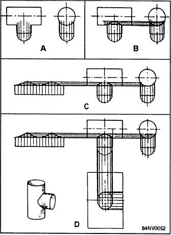
You should refer to this figure as you read the following
section. The T-joint consists of two cylinders with
equal diameters that intersect at right angles.
1. Draw a front view and a side view of the T-joint.
A bottom view representing the open end of the
other cylinder might also be drawn. Since this
cylinder is perfectly round, a semicircle may be
drawn attached to the front view. The division
points for the elements can be located on it (view
A).
2. Draw equally spaced divisions to locate the
elements. Project these divisions to both
cylinders. The points where the elements of one
cylinder intersect those of the other define the
intersection of the two cylinders (view B).
3. Draw the surface of the projecting pipe at one
side of the orthographic view so the length of
each element can be projected from the front
view (view C).
4. Draw the surface of the cross pipe below the
front view. Project lines down from the branch
pipe to locate the opening for it (view D).
When making the T-joint of two cylindrical pipes
Figure 14-46.--Development of a T-joint with two cylindrical
of unequal diameter, the procedure differs slightly.
pipes of unequal diameters.
Refer to figure 14-46 as you read the following section.
1. Draw the front and top orthographic views
1. Draw the orthographic views.
(view A). The ellipse formed by the top of the
2. Divide the smaller diameter branch pipe into
branch pipe may be omitted at this point and
equal parts. Draw the elements on this pipe in
drawn later.
both views (view A). The length of each
2. Draw the elements on the branch pipe in both
element is shown in the side view.
views (view B).
3. Project lines from the upper end of each element
3. Project lines down from the left end of each
in the side view to the front view (view B). The
element in the top view to the corresponding
intersections of these lines with the vertical lines
element in the front view. Draw the line of
drawn on the branch pipe define the intersection
intersection (view C).
of the two pipes.
4. Draw the ellipse formed by the end of the branch
4. Draw the line of intersection on the front view.
pipe in the top view. Do this by projecting lines
5. Draw the surface of the branch pipe to the left,
up from the upper end of each element in the
continuing the projection lines to locate the
front view to the corresponding element in the
element ends (view C).
top view (view D).
6. Draw the surface of the larger diameter main
5. Draw the pattern of the branch pipe to the right
pipe beneath the front view. Project lines down
and perpendicular to the pipe the same as in the
from the branch pipe to locate the opening for it
front view (view E).
(view D).
6. Draw the pattern for the main pipe to the left,
Figure 14-47 shows the following steps in drawing
with lines projecting from the intersection of the
a round pipe joint made up of two cylindrical pipes of
two pipes on the orthographic view to locate the
unequal diameters that intersect at an angle other than
opening for the branch pipe (view F).
90.
14-29