
Assemble the swage head assembly according to the
Pipe Inspection and Insertion Marking
manufacturer's directions and swage the fitting. After
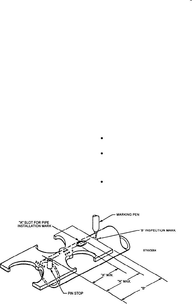
Using the proper marking/inspection gauge, verify
swaging, inspect the swage fitting dimensions
the OD of the pipe and fitting as shown in figure 16-25.
according to the latest manufacturer's technical manual.
The P-MAX gauge must fit over the pipe/fitting in the
region of the pipe/fitting contact; the P-MIN must not
ELASTIC STRAIN PRELOAD (ESP)
make three-point gauge contact or have two points 90
degrees apart. Check two places on the pipe 90 degrees
FITTINGS
apart for ovality. Refer to figure 16-26 for gauge usage.
After checking and verifying the pipe diameter and
ESP fittings provide the same advantage as the
roundness, use the marking/inspection gauge to lay out
SMF. There are many similarities in installation
the inspection and insertion marks. Refer to the
procedures of the two fittings. However, the basic
manufacturer's technical manual for proper insertion
design of the ESP fittings is different from that of the
depth. If the pipe wall thickness is greater than 0.125
SMF. The hydraulic pressure is applied in a horizontal
inch, use a scriber to mark the pipe. For pipe wall
position, as opposed to vertical. Their installation is
thickness of less than 0.125 or stainless steel material
use a chloride-free marking pen.
limited to copper pipe, class 200 90/10 copper nickel
pipe up to 2 l/2 inches nominal and 3 16 stainless steel
System Fit-up
l/4 inch schedule 80 pipe used in Halon systems. The
following equipment is necessary to install ESP fittings:
After marking the pipe, you are ready to install the
Locking power head--Consists of a stationary
SMF. Apply a lubricant compatible with the system
fluid to the pipe end and insert the pipe end into the
and a movable jaw assembly.
fitting. Keep rotation and twisting to a minimum when
Marking/inspection gauge--Used to verify the
inserting the pipe. A slight resistance should be
OD of pipe or tube, to locate installation and
encountered during insertion of the pipe into the fitting.
inspection marks, and to verify seal retention of
If no resistance is encountered, recheck the pipe to the
fitting match-up and the fitting for placement and
after-swage dimensions.
damage of the elastomeric seal. Position the end of the
Portable hydraulic power supply--Converts
fitting over the pipe installation mark so that some
mechanical, electrical, or pneumatic energy to
portion of the mark is visible. You must position the pipe
hydraulic energy.
in the fitting to ensure an acceptable joint (fig. 16-27).
Figure 16-25.--Using marking/inspection gauge to mark pipe.
16-24