
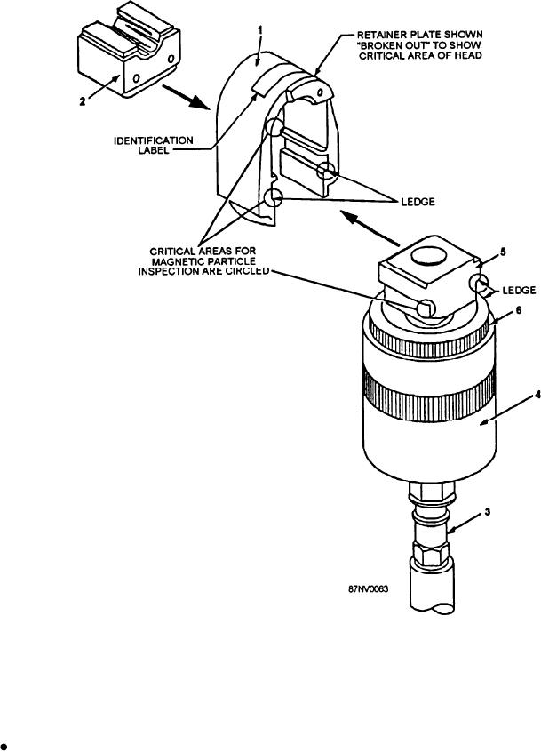
5 . Strut
3. Pressure line to hydraulic power supply
1. Yoke assembly
6. Knurled nut
4. Power unit
2. Die holder assembly (with lower die half shown)
Figure 16-24.--Swage tool component parts.
straight section of pipe with no wrinkles, bulges, or
Portable hydraulic power supply--Converts
dents. If the pipe is galvanized, you should remove the
mechanical, electrical, or pneumatic energy to
galvanization with emery cloth until a smooth round
hydraulic energy.
surface is obtained. The pipe end should be cut no more
than 3 degrees off square, but a cut of 5 degrees off
Pipe Preparation
square is acceptable. Apply a chamfer of l/16 inch at
approximately 30 degrees of the cut end and deburr the
Pipe end preparation is improtant to ensure a good
inside of the pipe, using 120 or 150 grit aluminum-oxide
contact area between the pipe and and the elastomeric
cloth to remove surface defects.
seal within the fitting. The SMF must be installed in a
16-23