
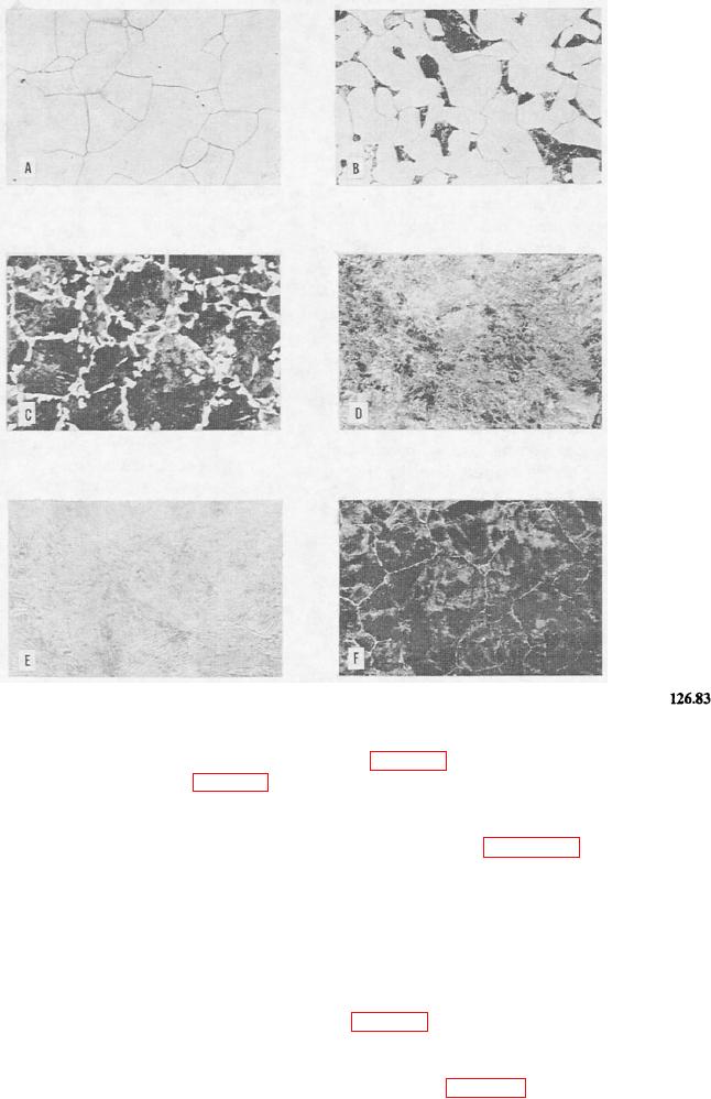
Figure 15-14.--Microstructural constituents of slowly cooled carbon steel (all etched with either picral or nital).
absorb a considerable amount as pure austenite, the
(ECF in fig. 15-11) will decompose partly or completely
maximum being about 2 percent at 2,065F (fig. 15-11,
into austenite and graphite.
point E). The solid solution of carbon in delta iron is
The part of the iron-carbon phase diagram that is
called delta ferrite, and the solid solution of carbon in
concerned with the heat treatment of steel is reproduced
alpha iron is called alpha ferrite, or, more simply, ferrite.
on an expanded scale in figure 15-13. Regardless of the
The physical process by which iron-carbon alloys,
carbon content, steel exists as austenite above line
especially those containing less than about 0.6 percent
GOSE. Steel of 0.83 percent carbon is designated as
of carbon, solidify is rather complicated. All you really
eutectoid steel, and those with lower or higher carbon
need to know, however, is that all iron-carbon alloys
as hypoeutectoid and hypereutectoid, respectively.
containing less than 2 percent of carbon (steel) will,
An eutectoid steel, when cooled at very slow rates
immediately or soon after solidification is complete,
from temperatures within the austenitic field, undergoes
consist of single-phase austenite. Cast irons containing
no change until the temperature reaches 1,330F (line
greater than 2 percent carbon will consist of two phases
PSK) (fig. 15-13). At this temperature (known as the A1
immediately after solidification-austenite and
temperature), the austenite transforms completely to a
cementite. Under some conditions this cementite
mixture of ferrite and cementite having a typical
formed on cooling through the temperature 2,065F
lamellar structure (fig. 15-14, view E). The mixture is
15-15