
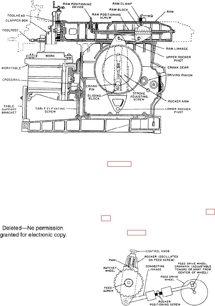
Figure 9-2.--Cross-sectional view of a crank-type shaper.
The worktable may be plain or universal, as shown
in figure 9-3. Some universal tables can be swiveled
only right or left, away from the perpendicular; others
may be tilted fore or aft at small angles to the ram.
T-slots on the worktables are for mounting the work or
work-holding devices. A table support bracket (foot)
holds the worktable and can be adjusted to the height
required. The bracket slides along a flat surface on the
base as the table moves horizontally. The table can be
adjusted vertically by the table elevating screw (fig.
TABLE FEED MECHANISM.--The table feed
mechanism (fig. 9-4) consists of a ratchet wheel and
Figure 9-3.--Swiveled and tilted table.
Figure 9-4.--Mechanical table feed mechanism.
9-3