
TM 55-2815-574-24
0157
INSTALLATION
1.
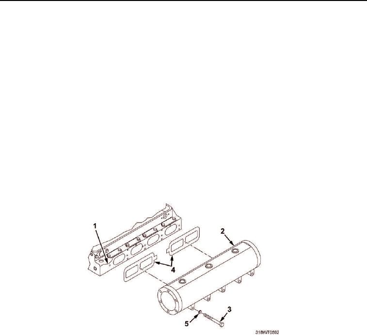
Position two new manifold gaskets (Figure 3, Item 4) on cylinder head (Figure 3, Item 1).
NOTE
Be sure locating pads on exhaust manifold rest on cylinder block locating pads.
2.
Install exhaust manifold (Figure 3, Item 2) on cylinder head (Figure 3, Item 1).
NOTE
Beveled washers should be set in position so that outer diameter will rest on manifold and
crown at center is next to nut.
3.
Install five bolts (Figure 3, Item 3) with beveled washers (Figure 3, Item 5) and secure exhaust manifold
(Figure 3, Item 2) on cylinder head (Figure 3, Item 1).
NOTE
Exhaust manifold nuts should be tightened from center of exhaust manifold outward,
alternating towards either end.
4.
Using torque wrench and socket set, torque bolts (Figure 3, Item 3) to 360 to 420 in-lb (41 to 47 Nm).
Figure 3. Exhaust Manifold.