Most bore gauges consist of a dial indicator,
extension pieces, bezel and locknut, spring-loaded
guide, and sensor button.
Before you start a measuring procedure, expose
both the bore gauge and the master ring gauge, or any
other tools used to preset the bore gauge, and the part to
be measured to the same work place environment for
one hour. If you fail to do this, a temperature differential
may cause your readings to be inaccurate. When you use
the bore gauge, touch only its insulated handle.
The gauge has two stationary spring-loaded points
and an adjustable point to permit a variation in range.
These points are evenly spaced to allow accurate
centering of the tool in the bore. A fourth point, the tip
of the dial indicator, is located between the two
stationary points. By simply rocking the tool in the bore,
you can observe the amount of variation on the dial.
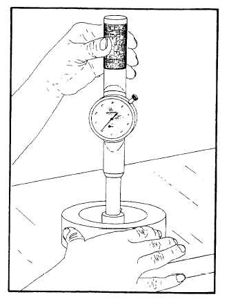
Figure 2-7 shows a bore gauge inside a bore being
moved in a gentle rocking motion. Always follow the
bore gauge manufacturer’s operating manual. Measure
the bore and mark the areas you measure. A good
Figure 2-7.—Measuring a bore with a bore gauge.
practice is to check the bore gauge in the standard after
you take each set of measurements to ensure that
readings are accurate.
STRAIN/DEFLECTION GAUGE
A strain or deflection gauge is used to check the
crankshaft alignment on large diesel engines. It is a
specially adapted dial indicator that fits between the
crank webs. The strain gauge reads the flexing motion
of the webs directly as the crankshaft is slowly rotated
(correct engine rotation). The gauge dial reads in
0.00l-inch graduations.
The strain gauge consists of a dial indicator, contact
point, balancing attachment, clamping nut, spring
plunger, rods and extension, and bezel.
Before you take a reading, be sure the engine is
completely assembled and cold. Place the strain gauge
between the webs of a crankthrow, as far as possible
from the axis of the crankpin. The ends of the indicator
should rest in the prick-punch marks in the crank webs.
If these marks are not present, consult the
manufacturer’s technical manual for the proper location
of the marks. Ensure that the strain gauge is at the same
temperature as the engine. A temperature differential
may cause inaccurate readings. Readings are generally
taken at the four crank positions; top dead center,
inboard, near or at bottom dead center, and outboard
However, the manufacturer’s technical manual for the
specific engine provides information concerning the
proper positions of the crank for taking readings. In
some situations, due to the position of the dial, you may
need to use a mirror and a flashlight to read the gauge.
Once you have placed the indicator in position for the
first reading, DO NOT touch the gauge until you have
taken and recorded all four readings. Variations in the
readings taken at the four crank positions indicate
distortion of the crank, which may be caused by any of
several factors, such as a bent crankshaft, worn bearings,
or improper engine alignment. The manufacturer’s
technical manual will provide you with the maximum
allowable deflection. Figure 2-8 shows the locations for
taking crankshaft deflection readings.
BORESCOPE
A borescope is used to inspect internal parts on an
engine without having to disassemble the engine. This
instrument helps a great deal in estimating the amount
of repair work needed and the time required for the
repair. Figure 2-9 shows a typical borescope.
2-5