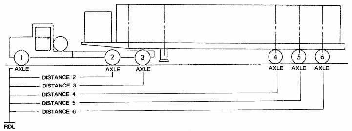
Naval Construction Force Embarkation Manual,COMSECOND/COMTHIRDNCBINST 3120.1 series.Alfa company is responsible for following theseprocedures that include the following: the removal ofdump truck headache racks, equipment exhauststacks, dozer blades, counterweights, and equipmentroll over protective structure (ROPS). Also, the fueltank of a vehicle to be embarked by airlift must bebetween one-fourth and three-fourths full; however,when the vehicle has to be placed on the ramp insidethe aircraft, the fuel tank should never be more thanone-third full. Accomplishment of these procedures isa major area of responsibility for the air detequipment platoon; therefore, make sure you knowwhere Alfa company placed the bolts, nuts, and partsfor the disassembled equipment because the air detwill be required to reassemble these items on site.After the CESE is cleaned, inspected, andserviced by Alfa company, the dispatcher notifies theMOCC that the CESE is ready to be transferred tothe Weighing and Marking station.WEIGHING AND MARKINGTo plan an airlift and to break down loads forindividual aircraft correctly, you must determine theweights and center of balance (C/B) of the two maindivisions: vehicles and general cargo.The weight and center of balance of vehiclesare determined with secondary loads (mobile loads)mounted. Mobile loads are items of baggage or cargotransported in truck beds and trailers that must beincluded in the total weight of a vehicle. To determinethe center of balance (C/B) on a vehicle, the 20thNaval Construction Regiment Embarkation Staff(R23), Gulfport, Mississippi, recommends thefollowing procedures:Step 1. Establish the reference datum line(RDL). The RDL is the farthest forward point of avehicle.Step 2. Measure distance 1 (D1). D1 is themeasurement in inches from the RDL to the centerline of the front axle.Step 3. Measure distance 2 (D2). D2 is themeasurement in inches from the RDL to the centerline of the intermediate axle or rear axle.NOTE: The distance 2 measurement locationfor vehicles with tandem axles is measured from theRDL to the trunnion.Step 4. Measure distance 3 (D3). D3 is themeasurement in inches from the RDL to the centerline of the rear axle. This step is performed onvehicles that have three or more axles and ontowed vehicles that will remain married (attached)to a vehicle when loaded on the aircraft. The axleson a towed vehicle will become D4, D5, and soforth (fig. 2-5).To perform Steps 5, 6, and 7, drive the vehicleonto portable scales (fig,. 2-6) placed under the tireson each axle.Figure 2-5.—CESE distance measurement locations.2-6
Integrated Publishing, Inc. - A (SDVOSB) Service Disabled Veteran Owned Small Business