stroke piston will cause tilt to be put on the tilt
plate, and the A-end will cause the mount to train
right.
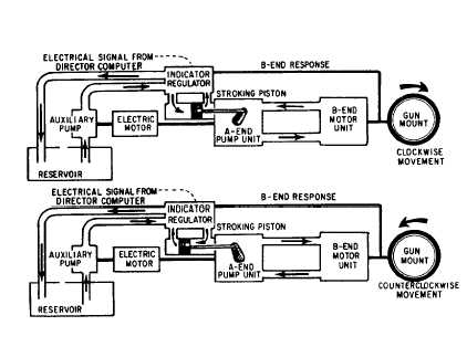
Figure 12-7 is a simplified block diagram
showing the main element of the hydraulic power
drive system under automatic control for
clockwise and counterclockwise rotation.
There are two principal problems in posi-
tioning a gun to fire. One is to get an accurate
gun-order signal. This problem is solved by the
director-computer combination. The other
problem is to transmit the director signal promptly
to the gun so that the position and movements
of the gun will be synchronized with the signals
from the director.
The problem of transforming gun-order
signals to mount movements is solved by the
power drive and its control—the indicator
regulator. The indicator regulator controls the
power drive, and this, in turn, controls the
movement of the gun.
The indicator regulator receives an initial
electrical gun-order from the director-computer,
compares it to the existing mount position, and
sends an error signal to the hydraulic control
mechanism in the regulator. The hydraulic control
mechanism controls the flow to the stroke control
shaft, which positions the tilting box in the A-end
of the transmission. Its tilt controls the volume
and direction of fluid pumped to the B-end and,
therefore, the speed and direction of the drive
shaft of the B-end. Through mechanical linkage,
the B-end output shaft moves the gun in the
direction determined by the signal. At the same
time, B-end response is transmitted to the
indicator regulator and continuously combines
with incoming gun-order signals to give the
error between the two. This error is modified
hydraulically, according to the system of
mechanical linkages and valves in the regulator.
When the gun is lagging behind the signal, its
movement is accelerated; and when it begins to
catch up, its movement is slowed down so that
it will not overrun excessively.
LANDING GEAR EMERGENCY
SYSTEM
If the landing gear in a naval aircraft fails to
extend to the down and locked position, the
aircraft has an emergency method to extend the
landing gear. This text will cover the nitrogen
system.
The nitrogen storage bottle system is a
one-shot system powered by nitrogen pressure
stored in four compressed nitrogen bottles
(fig. 12-8). When the landing gear control handle
is used to actuate the emergency landing gear
system, a cable between the control and the
manually operated nitrogen bottle opens the
emergency gear down release valve on the bottle.
Nitrogen from this bottle actuates the release
valves on the other three bottles so that they
discharge. Nitrogen flows from the manually
operated bottle, actuates the dump valves, and
causes the shuttles within the shuttle valves on the
Figure 12-7.—Operation of the hydraulic power drive.
12-8