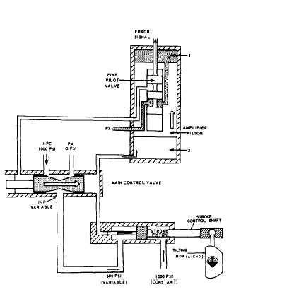
the pumps are designed to operate at a speed muchslower than that of the motor.The replenishing pump is a spur gear pump.Its purpose is to replenish fluid to the activesystem of the power drive. It receives its supplyof fluid from the reservoir and discharges it tothe B-end valve plate. This discharge of fluid fromthe pump is held at a constant pressure by theaction of a pressure relief valve. (Because thecapacity of the pump exceeds replenishingdemands, the relief valve is continuously allowingsome of the fluid to flow back to the reservoir.)The sump pump and oscillator has a twofoldpurpose. It pumps leakage, which collects in thesump of the indicator regulator, to the expansiontank. Additionally, it transmits a pulsating effectto the fluid in the response pressure system.Oscillations in the hydraulic response system helpeliminate static friction of valves, allowinghydraulic control to respond faster.The control pressure pump supplies high-pressure fluid for the hydraulic control system,brake pistons, lock piston, and the hand-controlled clutch operating piston. The controlpressure pump is a fixed-displacement, axial-piston type. An adjustable relief valve is used tolimit the operating pressure at the outlet of thepump.ControlFor the purpose of this text, control constitutesthe relationship between the stroke control shaftand the tilting box. The stroke control shaft is oneof the piston rods of a double-acting piston-typeactuating cylinder. This actuating cylinder and itsdirect means of control are referred to as the maincylinder assembly (fig. 12-6). It is the link betweenthe hydraulic followup system and the power driveitself.In hand control, the tilting box is mechanicallypositioned by gearing from the handwheelthrough the A-end control unit. In local andautomatic control, the tilting box is positioned bythe stroke control shaft. As shown in figure 12-6,the extended end of the control shaft is connectedto the tilting box. Movement of the shaft will pivotthe tilting box one way or the other; which, inturn, controls the output of the A-end of thetransmission. The other end of the shaft isattached to the main piston. A shorter shaft isattached to the opposite side of the piston. Thisshaft is also smaller in diameter. Thus the workingarea of the left side of the piston is twice that of thearea of the right side, as it appears in figure 12-6.Figure 12–6.–Main cylinder assembly.Intermediate high-pressure fluid (IHP) istransmitted to the left side of the piston, whilehigh-pressure hydraulic fluid (HPC) is transmittedto the right side. The HPC is held constant at 1000psi. Since the area of the piston upon which HPCacts is exactly one-half the area upon which IHPacts, the main piston is maintained in a fixedposition when IHP is one-half HPC (500 psi).Whenever IHP varies from its normal value of500 psi, the main piston will move, thus movingthe tilting box.OperationAssume that a right train order signal isreceived. This will cause the pilot valve to bepulled upward. The fluid in the upper chamberof the amplifier piston can now flow through thelower land chamber of the fine pilot to exhaust.This will cause the amplifier piston to moveupward, and the fluid in the right-hand chamberof the main control valve can flow into the lowerchamber of the amplifier valve.The main control valve will now move to theright, IHP will drop below 500 psi, and the strokepiston will move to the left. Movement of the12-7
Integrated Publishing, Inc. - A (SDVOSB) Service Disabled Veteran Owned Small Business