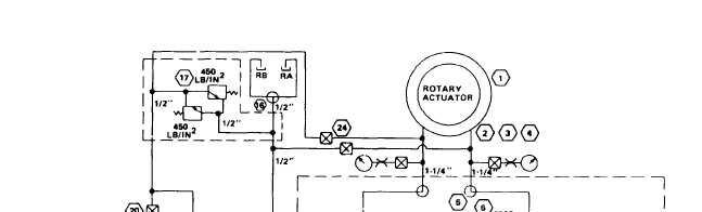
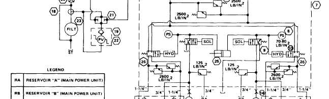
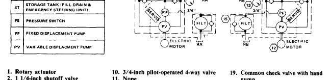
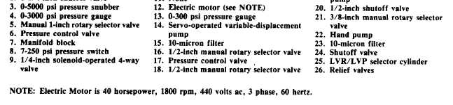
Graphic DiagramsThe primary purpose of a graphic (schematic)diagram is to enable the maintenance person totrace the flow of fluid from component tocomponent within the system. This type ofdiagram uses standard symbols to show eachcomponent and includes all interconnectingpiping. Additionally, the diagram contains acomponent list, pipe size, data on the sequenceof operation, and other pertinent information.The graphic diagram (fig. 12-3) does not indi-cate the physical location of the various com-ponents, but it does show the relation of eachcomponent to the other components within thesystem.,Figure 12-3.—Graphic diagram of LST 1182 class hydraulic steering gear.12-4
Integrated Publishing, Inc. - A (SDVOSB) Service Disabled Veteran Owned Small Business