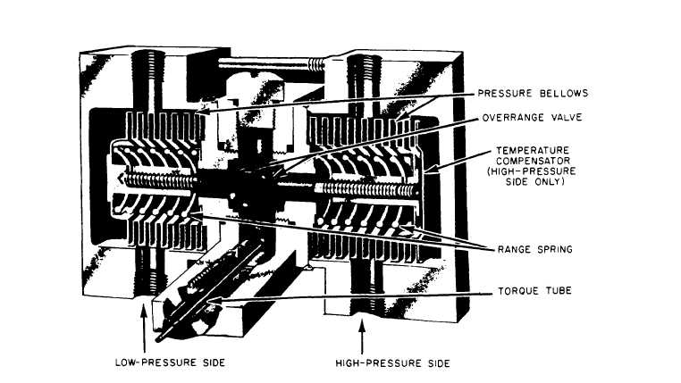
Figure 8-8.–Dual bellows assembly.
When in operation, the bellows will move in
proportion to the difference in pressure applied
across the bellows unit assembly. The linear
motion of the bellows is picked up by a drive arm
and transmitted as a rotary motion through a
torque tube assembly (fig. 8-8). The indicating
mechanism multiplies rotation of the torque tube
through a gear and pinion to the indicating
pointer.
Bellows elements are used in various appli-
cations where the pressure-sensitive device must
be powerful enough to operate not only the
indicating pointer but also some type of recording
device.
PRESSURE SWITCHES
Often when a measured pressure reaches a
certain maximum or minimum value, it is desir-
able to have an alarm sound a warning, a light
to give a signal, or an auxiliary control system to
energize or de-energize. A pressure switch is the
device commonly used for this purpose.
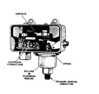
One of the simplest pressure switches is the
single-pole, single-throw, quick-acting type shown
in figure 8-9. This switch is contained in a metal
Figure 8-9.—Typical pressure switch.
8-5