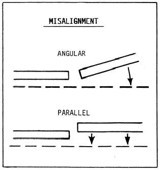
all points. In service, the best indication of goodalignment is good tooth contact.The technical manual furnished with each gearinstallation describes the procedures for determining theproper depth of mesh and parallelism of gear and pinionshafts. The length of tooth contact across the face of thegear teeth is the key to satisfactory alignment ofreduction gears.Poor alignment between the line shaft and the MRGmay be detected at the reduction gear. Uneven loadingof the low-speed gear train and noisy operation in certainspeed ranges are two common results of poor line shaftto MRG alignment.The most favorable alignment position of the mainengine to the reduction gear is when they are concentricat full power at the proper operating temperature. Theflexible high-speed coupling is designed to handle thetransient condition of slight misalignments as themachinery comes up to temperature. The two mostcommon forms of misalignment between the primemover and the driven shafts are angular and paralleloffset, as shown in figure 3-5.The object of the alignment is to locate the turbineso the axis of the spindle will be concentric with andparallel to the axis of the reduction gear input pinionshaft. Attaining alignment is complicated by the factthat the turbine, reduction gear, and foundations allFigure 3-5.—Angular and parallel misalignment.expand as they are heated during operation to the hotrunning conition. Another factor is when operatingpinion shafts move higher in their bearings under theinfluence of the hydrodynamic oil film and toothpressure. These changes in position have beenpredetermined by the manufacturer, and you can findthe offset readings in the appropriate technical manualfor the installation.MAIN THRUST BEARING CLEARANCEMEASUREMENTSAs you have already learned in Gas TurbineSystems Technician (Electrical) 3/Gas Turbine SystemsTechnician (Mechanical) 3, volume 1, NAVEDTRA10563, propeller thrust is transferred from eachpropulsion shaft to the hull through a Kingsbury mainthrust bearing (fig. 3-6). The Kingsbury thrust bearinguses the wedge-shaped oil film lubrication principle.This principle is based on an oil film between twosliding surfaces tends to assume a tapered depth with thethicker film at the entering side. In a Kingsburyassembly, eight bearing shoes are installed on each sideof the thrust collar. Therefore, eight separatewedge-shaped oil films are installed on each thrust face.Since the bearing shoes are free to tilt slightly, the oilautomatically assumes the taper required by shaft speed,loading, and oil viscosity.The main thrust bearing assembly consists of thebearing housing, two thrust rings, and a thrust collar.The housing, thrust rings, and thrust collar facings areall split horizontally. Each thrust ring is made up of 8steel thrust shoes with tin babbitt facings, 16 levelingplates, and a retainer ring. The thrust collar has atwo-piece removable steel thrust face attached to eachside. Each thrust shoe contains a hardened shoe supportwith a spherical face. The support bears on the upperleveling plate and the spherical face allow the thrustshoe to pivot or tilt slightly in all directions. Thisarrangement allows the bearing to operate on thefree-wedge film lubrication principle. One thrust shoeon each side is fitted with a resistance temperatureelement (RTE).Due to the spring isolation system, main thrustbearing clearance measurements are no longer takenwith a depth micrometer. All measurements are nowtaken with a dial indicator that measures the deflectionof the propulsion shaft at the main flange. There are twomethods (static and dynamic) used to create shaftdeflection. The method used depends on the ship class.The static method must be used on CG-66 and aboveand all DDG-51 class ships. The dynamic method is3-6
Integrated Publishing, Inc. - A (SDVOSB) Service Disabled Veteran Owned Small Business