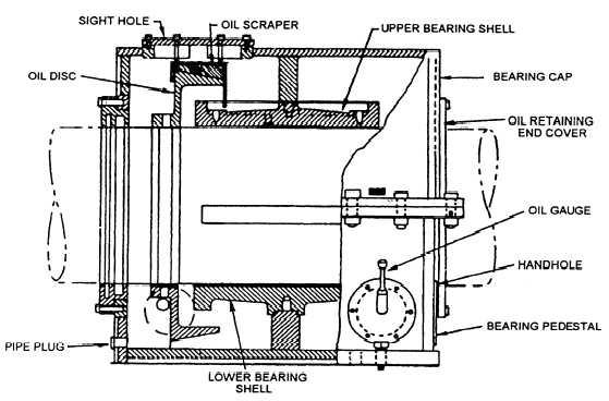
An oil disc (ring) clamped to the shaft is used in each
bearing to deliver oil to the upper bearing and journal
surfaces. As the disc rotates, it picks up oil from the
bearing reservoir and carries it to the oil scraper on the
upper shell. The scraper removes oil from the disc and
directs it to the upper bearing lining. A clear sight cover
on the bearing housing allows visual confirmation of the
oil disc operation. Figure 3-7 shows a typical disc-oiled
line shaft bearing.
All bearing pedestals have an oil level rod and an
oil reservoir thermometer for checking oil level and
temperature. A resistance temperature detector (RTD)
is installed in the lower bearing shell of each
oil-lubricated bearing. The RTDs provide for remote
readouts of each bearing’s temperature on the digital
demand displays.
Clearances are taken with a depth micrometer
through a port in the upper bearing housing, which
contains the anti-rotation pin. The original installation
readings are stamped into the flat surface adjacent to this
port. You must take readings according to PMS
requirements or when an abnormal condition exists.
For information on maximum wear limits and repair
procedures, you should consult the appropriate
manufacturer’s technical manual and NSTM, chapter
244, “Shafting, Bearings, and Seals.”
STRUT AND STERN TUBE BEARINGS
Each propeller shaft extending aft of the stern tube
is supported by two struts, each containing a
seawater-cooled bearing. Figure 3-8 shows a typical
strut bearing.
Stern tube bearings are in constant contact with the
seawater surrounding the stern tubes. The clean
seawater that passes through the stem tube seals from
the ship’s seawater service system or firemain system
(in emergencies) also flows through the stern tube
bearings. Stern tube bearings are identical to forward
strut bearings. However, aft strut bearings are roughly
5 inches larger in diameter and twice as long as stem
tube bearings. Remember that stem tube bearings are
not remotely monitored.
PROPULSION SYSTEMS
The ship’s propulsion thrust is provided by
hydraulically actuated propellers. In the Gas Turbine
Systems Technician (Electrical) 3/Gas Turbine Systems
Technician (Mechanical) 3, volume 1, NAVEDTRA
10563, you were provided with a complete description
of propulsion systems and how they operate. As a gas
turbine supervisor you need to be knowledgeable and
experienced with a variety of gas turbine propulsion
Figure 3-7.—Disc-oiled line shaft bearing,
3-11