
Figure 14-20.--Profiling a bevel gear.
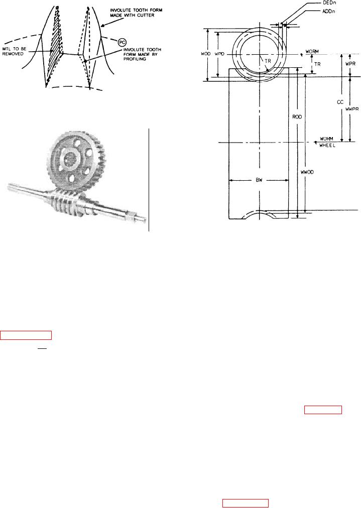
WOD - Worm outside diameter
WPD - Worm pitch diameter
Figure 14-21.--Worm and worm gear.
DEDn - Dedendum
ADDn - Addendum
TR - Throat radius
WPR - Worm pitch radius
Remember, you cannot machine a perfect bevel
CC - Center-to-center distance
gear in a milling machine. As you learned earlier, you
ROD - Rim outside diameter
only use part of the cutter's contour when you machine
WWOD - Worm wheel outside diameter
the small end of the tooth. So, to finish the bevel gear
WWPR - Worm wheel pitch radius
teeth properly, you must file the contour as illustrated
BW - Blank width
in figure 14-20 . This is known to a Machinery
Figure 14-22.--Parts of a worm and worm gear.
Repairman as profiling the gear.
To file a tooth, start at the top of the large end of the
tooth and gradually work to the pitch line at the small
A worm, sometimes called a worm thread,
end.
resembles an Acme thread. Worms can be either solid
After you have determined that the gear is properly
or cylinder-type mounted on a shaft. Both are installed
formed, give the gear a final touch by deburring it.
perpendicular to the worm gear (fig. 14-21). Worms
may have single, double, or triple threads. One
revolution of a worm with a single thread turns the
WORMS AND WORM GEARS
circumference of the worm gear an amount equal to the
A worm gear is sometimes called a worm wheel. It
distance between identical points on two adjacent teeth,
has teeth cut at an angle to the axis of rotation and
or one circular pitch, and so on.
radially in the gear face. The teeth are helical and
This type of gearing is also known as an "endless
conform to the helix angle of the teeth on the worm.
screw," where the worm is the driver and the worm gear
Worm gears are used for heavy-duty work where a
is driven. Figure 14-22 identifies the parts of a worm
large reduction of speed is required. They are used
and a worm wheel.
extensively in speed reducers.
14-22

