
TM 55-2815-574-24
0121
REMOVAL
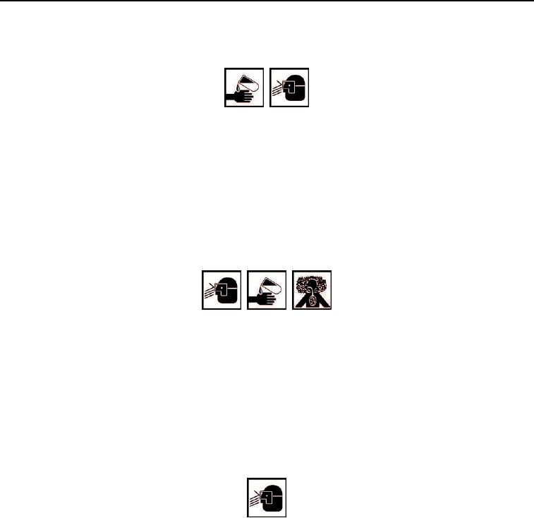
WARNING
Fuel/Oil may cause irritation to eyes or skin. Wear protective goggles, gloves, and clothing.
Failure to comply may result in personnel injury or death.
1.
While holding nut (Figure 1, Item 7) and washer (Figure 1, Item 6), remove bolt (Figure 1, Item 2), washer
(Figure 1, Item 3), and spacer (Figure 1, Item 4) from screen (Figure 1, Item 5).
2.
Remove screen (Figure 1, Item 5) from cover (Figure 1, Item 1).
END OF TASK
CLEANING
WARNING
Cleaning compound (MIL-PRF-29602) may cause irritation to the eyes or skin. Use in
well-ventilated areas and keep away from heat and open flame. Wear protective goggles
and clothing. In case compound comes in contact with:
Eyes, flush immediately with water.
Skin, wash with soap and water.
Failure to comply may result in personnel injury or death.
1.
Using cleaner and cleaning cloth, clean nut (Figure 1, Item 7), washer (Figure 1, Item 6), bolt
(Figure 1, Item 2), washer (Figure 1, Item 3), spacer (Figure 1, Item 4), and screen (Figure 1, Item 5).
WARNING
Do not exceed 40 PSI (280 kPa) when using compressed air for drying components.
Failure to comply may result in serious injury to personnel.
2.
Using compressed air, dry all parts.
END OF TASK
INSPECTION
1.
Inspect screen (Figure 1, Item 5) for cracks, distortion, holes, tears, deterioration, and rust. Replace as
necessary.
2.
Inspect cover (Figure 1, Item 1) for cracks, distortion, holes, tears, deterioration, and rust. Replace as
necessary.
0121-2