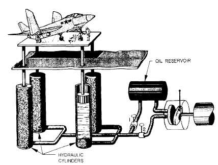
Figure 10-12.-Hydraulic lift.
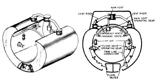
Figure 10-13.-Submarine special ballast tank (safety tank).
compressed air. Sufficient air is left trapped in the tanks
to prevent the seawater from reentering.
We use other tanks, such as variable ballast tanks
and special ballast tanks (for example, the negative tank,
safety tank, and bow buoyancy tank), either for
controlling trim or stability or for emergency weight-
compensating purposes. The variable ballast tanks have
no direct connection to the sea. Therefore, we must
pump water into or out of them. The negative tank and
the safety tank can open to the sea through large flood
valves. These valves, as well as the vent valves for the
main ballast tanks and those for the safety and negative
tanks, are all hydraulically operated.
The vents and flood valves are outside the pressure
hull, so some means of remote control is needed to open
and close them from within the submarine. We use
hydraulic pumps, lines, and rams for this purpose. Oil
pumped through tubing running through the pressure
hull actuates the valve’s operating mechanisms by
exerting pressure on and moving a piston in a hydraulic
cylinder. Operating the valves by a hydraulic system
from a control room is easier and simpler than doing so
by a mechanical system of gears, shafts, and levers. The
hydraulic lines can be readily led around corners and
obstructions, and a minimum of moving parts is
required.
Figure 10-13 is a schematic sketch of the safety
tank-one of the special ballast tanks in a submarine.
The main vent and the flood valves of this tank operate
10-9