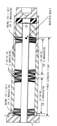
Figure 12-64.-Buffer bolt.
small plungers.
A weighted piston rests on these
plungers. Ajar of the hammer while in operation forces
the piston and plunger down and thus drives a small
amount of oil past the ball check valves and into the feed
lines. Two of the feed lines have terminal checks that
hold back the high pressure of the combustion chamber.
A small pipe plug is provided at each terminal to observe
the flow of oil.
NOTE: Fill the oil reservoir with high temperature,
high detergent No. 30 to No. 40 viscosity diesel engine
lubricating oil with a flash point of 425° to 450°.
CYLINDER.— The cylinder is a stress-relieved
weldment made from steel tubing and plate with a bore
specifically chrome-plated to prevent seizing, galling,
and rapid wear. The shape of the shell forms a fuel and
oil tank as well as protection for the fuel and oil pumps,
lines, and trip mechanism. Cover plates, front and back
provide easy access to the components. For safety in
transporting and rigging the hammer, the ram piston is
locked in place by a travel plug found midway on the
front of the hammer. This plug should be removed when
the hammer is rigged and ready for operation and should
Figure 12-65.-Maximum ram-piston overstroke.
be replaced when the hammer is removed from the leads
or is laid horizontal. The ram piston is a chrome-steel
forging that has eight compression rings.
BASE ASSEMBLY.— The anvil block in the base
assembly group is held in place by buffer bolts and has
compression rings identical to those on the ram piston
(fig. 12-64). Radial thrust or side thrust to the hammer
is transmitted to the leads through the thrust bearing. A
vibration damper, concealed under a shroud, isolates the
cylinder from the shock vibration of the anvil. Buffer
bumpers absorb the recoil from the Belleville washer
type of buffer springs connected to the anvil by buffer
bolts, dampening overtravel and holding the hammer
together. Pins lock the buffer compression nuts to the
buffer bolts and are held captive by the buffer housing
12-46


