Figure 9-38.-Backhoe boom arm pivot point.
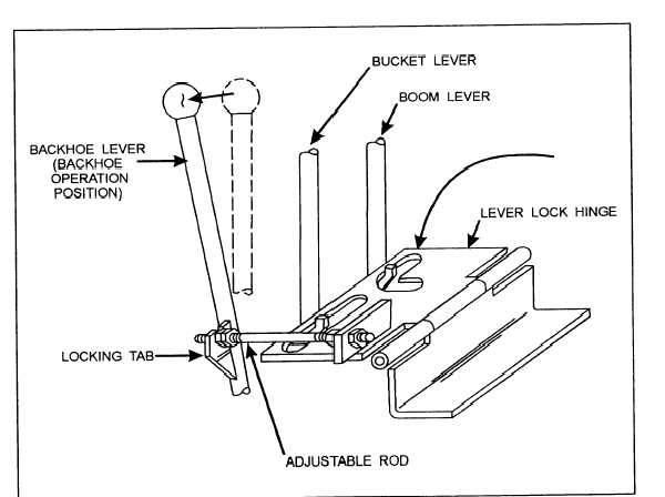
Figure 9-39.—Backhoe operation locking lever locking plate.
boom arm pivot point is approximately 20 inches from
3. For backhoe operations, place the two levers
the ground, as shown in figure 9-38.
fiut.best from the operator in the hold position. Place the
lever closest to the operator in the forward position.
2. Using the
main frame until
with the ground.
bucket control lever, tilt the backhoe
Move the locking plate in the position shown in
the top of the main frame is parallel
figure 9-39, locking the lever in the forward position
and the two other levers in the hold position.
9-15
.