Figure 4-15 is a series of drawings that illustrates
how the universal joint is used in the operation
of this pump.
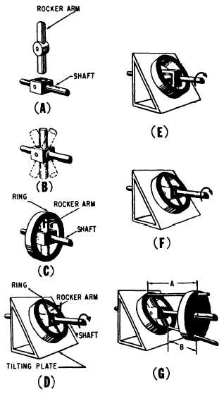
First, a rocker arm is installed on a horizontal
shaft. (See fig. 4-15, view A.) The arm is joined
to the shaft by a pin so that it can be swung back
and forth, as indicated in view B. Next, a ring is
placed around the shaft and secured to the rocker
arm so the ring can turn from left to right as
shown in view C. This provides two rotary
motions in different planes at the same time and
in varying proportions as may be desired. The
rocker arm can swing back and forth in one arc,
and the ring can simultaneously move from left
Figure 4-15.–Relationship of the universal joint in operation
of the axial piston pump.
to right in another arc, in a plane at right angles
to the plane in which the rocker arm turns.
Next, a tilting plate is added to the assembly.
The tilting plate is placed at a slant to the axis
of the shaft, as depicted in figure 4-15, view D.
The rocker arm is then slanted at the same angle
as the tilting plate, so that it lies parallel to the
tilting plate. The ring is also parallel to, and in
contact with, the tilting plate. The position of the
ring in relation to the rocker arm is unchanged
from that shown in figure 4-15, view C.
Figure 4-15, view E, shows the assembly after
the shaft, still in a horizontal position, has been
rotated a quarter turn. The rocker arm is still in
the same position as the tilting plate and is now
perpendicular to the axis of the shaft. The ring
has turned on the rocker pins, so that it has
changed its position in relation to the rocker arm,
but it remains parallel to, and in contact with, the
tilting plate.
View F of figure 4-15 shows the assembly after
the shaft has been rotated another quarter turn.
The parts are now in the same position as shown
in view D, but with the ends of the rocker arm
reversed. The ring still bears against the tilting
plate.
As the shaft continues to rotate, the rocker
arm and the ring turn about their pivots, with each
changing its relation to the other and with the ring
always bearing on the plate.
Figure 4-15, view G, shows a wheel added to
the assembly. The wheel is placed upright and
fixed to the shaft, so that it rotates with the shaft.
In addition, two rods, A and B, are loosely
connected to the tilting ring and extend through
two holes standing opposite each other in the fixed
wheel. As the shaft is rotated, the fixed wheel
turns perpendicular to the shaft at all times. The
tilting ring rotates with the shaft and always
remains tilted, since it remains in contact with the
tilting plate. Referring to view G, the distance
along rod A, from the tilting ring to the fixed
wheel, is greater than the distance along rod B.
As the assembly is rotated, however, the distance
along rod A decreases as its point of attachment
to the tilting ring moves closer to the fixed wheel,
while the distance along rod B increases. These
changes continue until after a half revolution, at
which time the initial positions of the rods have
been reversed. After another half revolution, the
two rods will again be in their original positions.
As the assembly rotates, the rods move in and
out through the holes in the fixed wheel. This is
the way the axial piston pump works. To get a
pumping action, place pistons at the ends of the
4-13