rods, beyond the fixed wheel, and insert them into
cylinders. The rods must be connected to the
pistons and to the wheel by ball and socket joints.
As the assembly rotates, each piston moves back
and forth in its cylinder. Suction and discharge
lines can be arranged so that liquid enters the
cylinders while the spaces between the piston
heads and the bases of the cylinders are increasing,
and leaves the cylinders during the other half of
each revolution when the pistons are moving in
the opposite direction.
The main parts of the pump are the drive
shaft, pistons, cylinder block, and valve and swash
plates. There are two ports in the valve plate.
These ports connect directly to openings in the
face of the cylinder block. Fluid is drawn into one
port and forced out the other port by the
reciprocating action of the pistons.
IN-LINE VARIABLE-DISPLACEMENT
AXIAL PISTON PUMP.— When the drive shaft
is rotated, it rotates the pistons and the cylinder
block with it. The swash plate placed at an angle
causes the pistons to move back and forth in the
cylinder block while the shaft, piston, cylinder
block, and swash plate rotate together. (The shaft,
piston, cylinder block, and swash plate together
is sometimes referred to as the rotating group or
assembly.) As the pistons reciprocate in the
cylinder block, fluid enters one port and is forced
out the other.
Figure 4-13 shows piston A at the bottom of
its stroke. When piston A has rotated to the
position held by piston B, it will have moved
upward in its cylinder, forcing fluid through the
outlet port during the entire distance. During the
remainder of the rotation back to it original
position, the piston travels downward in the
cylinder. This action creates a low-pressure area
in the cylinder. The difference in pressure between
the cylinder inlet and the reservoir causes fluid
to flow into the inlet port to the cylinder. Since
each one of the pistons performs the same
operation in succession, fluid is constantly being
taken into the cylinder bores through the inlet port
and discharged from the cylinder bores into
the system. This action provides a steady,
nonpulsating flow of fluid.
The tilt or angle of the swash plate determines
the distance the pistons move back and forth in
their cylinders; thereby, controlling the pump
output.
When the swash plate is at a right angle to the
shaft, and the pump is rotating, the pistons do
not reciprocate; therefore, no pumping action
takes place. When the swash plate is tilted away
from a right angle, the pistons reciprocate and
fluid is pumped.
Since the displacement of this type of pump
is varied by changing the angle of the tilting box,
some means must be used to control the changes
of this angle. Various methods are used to control
this movement—manual, electric, pneumatic, or
hydraulic.
STRATOPOWER PUMP.— Another type of
axial piston pump, sometimes referred to as an
in-line pump, is commonly referred to as a
Stratopower pump. This pump is available
in either the fixed-displacement type or the
variable-displacement type.
Two major functions are performed by the
internal parts of the fixed-displacement Strato-
power pump. These functions are mechanical
drive and fluid displacement.
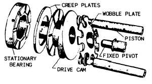
The mechanical drive mechanism is shown in
figure 4-16. In this type of pump, the pistons and
block do not rotate. Piston motion is caused by
rotating the drive cam displacing each piston the
full height of the drive cam during each revolution
of the shaft. The ends of the pistons are attached
to a wobble plate supported by a freed center pivot
and are held inconstant contact with the cam face.
As the high side of the rotating drive cam
depresses one side of the wobble plate, the other
side of the wobble plate is withdrawn an equal
amount, moving the pistons with it. The two creep
plates are provided to decrease wear on the
revolving cam.
A schematic diagram of the displacement of
fluid is shown in figure 4-17. Fluid is displaced
by axial motion of the pistons. As each piston
advances in its respective cylinder block bore,
pressure opens the check valve and a quantity of
fluid is forced past it. Combined back pressure
and check valve spring tension close the check
Figure 4-16.—Mechanical drive—Stratopower pump.
4-14