The output piston can be raised higher and
maintained at this height if additional components
are installed as shown in figure 2-20. In this
illustration the jack is designed so that it can be
raised, lowered, or held at a constant height.
These results are attained by introducing a number
of valves and also a reserve supply of fluid to be
used in the system.
Notice that this system contains the five basic
components—the reservoir; cylinder 1, which
serves as a pump; valve 3, which serves as a
directional control valve; cylinder 2, which serves
as the actuating device; and lines to transmit the
fluid to and from the different components. In
addition, this system contains two valves, 1 and
2, whose functions are explained in the following
discussion.
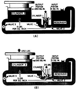
As the input piston is raised (fig. 2-20, view
A), valve 1 is closed by the back pressure from
the weight of the output piston. At the same time,
valve 2 is opened by the head of the fluid in the
reservoir. This forces fluid into cylinder 1. When
the input piston is lowered (fig. 2-20, view B), a
pressure is developed in cylinder 1. When this
pressure exceeds the head in the reservoir, it closes
valve 2. When it exceeds the back pressure from
the output piston, it opens valve 1, forcing fluid
into the pipeline. The pressure from cylinder 1 is
Figure 2-20.—Hydraulic jack; (A) up stroke; (B) downstroke.
thus transmitted into cylinder 2, where it acts to
raise the output piston with its attached lift
platform. When the input piston is again raised,
the pressure in cylinder 1 drops below that in
cylinder 2, causing valve 1 to close. This prevents
the return of fluid and holds the output piston
with its attached lift platform at its new level.
During this stroke, valve 2 opens again allowing
a new supply of fluid into cylinder 1 for the next
power (downward) stroke of the input piston.
Thus, by repeated strokes of the input piston, the
lift platform can be progressively raised. To lower
the lift platform, valve 3 is opened, and the fluid
from cylinder 2 is returned to the reservoir.
HYDRAULIC BRAKES
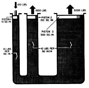
The hydraulic brake system used in the
automobile is a multiple piston system. A multiple
piston system allows forces to be transmitted to
two or more pistons in the manner indicated in
figure 2-21. Note that the pressure set up by the
force applied to the input piston (1) is transmitted
undiminished to both output pistons (2 and 3),
and that the resultant force on each piston is
proportional to its area. The multiplication of
forces from the input piston to each output piston
is the same as that explained earlier.
The hydraulic brake system from the master
cylinders to the wheel cylinders on most
Figure 2-21.—Multiple piston system.
2-16