can be kept clean inside and variations from
normal operation can easily be detected and
remedied.
OPERATION OF HYDRAULIC
COMPONENTS
To transmit and control power through
pressurized fluids, an arrangement of inter-
connected components is required. Such an
arrangement is commonly referred to as a system.
The number and arrangement of the components
vary from system to system, depending on the
particular application. In many applications, one
main system supplies power to several subsystems,
which are sometimes referred to as circuits. The
complete system may be a small compact unit;
more often, however, the components are located
at widely separated points for convenient control
and operation of the system.
The basic components of a fluid power system
are essentially the same, regardless of whether the
system uses a hydraulic or a pneumatic medium.
There are five basic components used in a system.
These basic components are as follows:
1.
2.
3.
4.
5.
Reservoir or receiver
Pump or compressor
Lines (pipe, tubing, or flexible hose)
Directional control valve
Actuating device
Several applications of fluid power require
only a simple system; that is, a system which uses
only a few components in addition to the five
basic components. A few of these applications are
presented in the following paragraphs. We will
explain the operation of these systems briefly at
this time so you will know the purpose of each
component and can better understand how
hydraulics is used in the operation of these
systems. More complex fluid power systems are
described in chapter 12.
HYDRAULIC JACK
The hydraulic jack is perhaps one of the
simplest forms of a fluid power system. By
moving the handle of a small device, an individual
can lift a load weighing several tons. A small
initial force exerted on the handle is transmitted
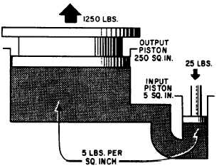
by a fluid to a much larger area. To understand
this better, study figure 2-19. The small input
piston has an area of 5 square inches and is
directly connected to a large cylinder with an
output piston having an area of 250 square inches.
The top of this piston forms a lift platform.
If a force of 25 pounds is applied to the input
piston, it produces a pressure of 5 psi in the fluid,
that is, of course, if a sufficient amount of
resistant force is acting against the top of the
output piston. Disregarding friction loss, this
pressure acting on the 250 square inch area of the
output piston will support a resistance force of
1,250 pounds. In other words, this pressure could
overcome a force of slightly under 1,250 pounds.
An input force of 25 pounds has been transformed
into a working force of more than half a ton;
however, for this to be true, the distance traveled
by the input piston must be 50 times greater than
the distance traveled by the output piston. Thus,
for every inch that the input piston moves, the
output piston will move only one-fiftieth of an
i n c h .
This would be ideal if the output piston needed
to move only a short distance. However, in most
instances, the output piston would have to be
capable of moving a greater distance to serve a
practical application. The device shown in figure
2-19 is not capable of moving the output piston
farther than that shown; therefore, some other
means must be used to raise the output piston to
a greater height.
Figure 2-19.—Hydraulic jack.
2-15