manner. Another reason for not leaving globe
valves in the fully open position is that it is
sometimes difficult to determine if the valve is
open or closed. If the valve is jammed in the open
position, the stem may be damaged or broken by
someone who thinks the valve is closed, and
attempts to open it.
It is important that globe valves be installed
with the pressure against the face of the disk to
keep the system pressure away from the stem
packing when the valve is shut.
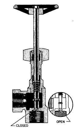
NEEDLE VALVES
Needle valves are similar in design and
operation to the globe valve. Instead of a disk,
a needle valve has a long tapered point at the end
of the valve stem. A cross-sectional view of a
needle valve is illustrated in figure 6-8.
The long taper of the valve element permits
a much smaller seating surface area than that of
the globe valve; therefore, the needle valve is more
suitable as a throttle valve. Needle valves are used
to control flow into delicate gauges, which
might be damaged by sudden surges of fluid under
pressure. Needle valves are also used to control
the end of a work cycle, where it is desirable for
motion to be brought slowly to a halt, and at other
points where precise adjustments of flow are
necessary and where a small rate of flow is
desired.
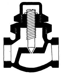
Although many of the needle valves used in
fluid power systems are the manually operated
type (fig. 6-8), modifications of this type of valve
are often used as variable restrictors. This valve is
constructed without a handwheel and is adjusted
to provide a specific rate of flow. This rate of flow
will provide a desired time of operation for a
particular subsystem. Since this type of valve can
be adjusted to conform to the requirements of a
particular system, it can be used in a variety of
systems. Figure 6-9 illustrates a needle valve that
was modified as a variable restrictor.
HYDRAULIC AND PNEUMATIC
GLOBE VALVES
The valve consists of a valve body and a stem
cartridge assembly. The stem cartridge assembly
includes the bonnet, gland nut, packing, packing
retainer, handle, stem, and seat. On small valves
(1/8 and 1/4 inch) the stem is made in one piece,
but on larger sizes it is made of a stem, guide,
and stem retainer. The valve disk is made of nylon
and is swaged into either the stem, for 1/8- and
1/4-inch valves, or the guide, for larger valves.
The bonnet screws into the valve body with
left-hand threads and is sealed by an O-ring
(including a back-up ring).
Figure 6-8.—Cross-sectional view of a needle valve.
Figure 6-9.—Variable restrictor.
6-5