viewed through wide angle probe No. 2. When
circumferential cracking is observed, record the band
number and the span of the cracking relative to the
number of cooling/dilution holes. Use the diameter
of the cooling holes as a comparative measurement
gauge.
Axial Cracks. — Axial cracking usually starts at
band No. 3 on the inner liners and propagates aft and
forward. As operating time is accrued, these axial
panel cracks grow into three-legged cracks as seen in
figure 2-23. The edges of these cracks will separate
and the corners will lift into the flow path. Inspect the
areas aft and forward of these cracks, recording the
axially separated cracks that show a tendency to grow
together.
DOD is the primary cause of damage to the HP
nozzle and turbine rotor elements. It is caused by pieces
from the combustor liners cracking out of the panel
overhangs and impacting with the rotating turbine
elements. The most serious problem is the separation of
a large section of liner that could cause significant
damage. This usually occurs as a result of axial and
circumferential cracks growing together as shown in
figure 2-24. It is important to record the damage to
adjacent areas of about 5 inches to either side of the
damaged area.
These areas can grow together and
l i b e r a t e l a r g e p i e c e s o f m a t e r i a l .
T h e s e
circumferentially spaced, cracked areas are usually
separated at every other fuel nozzle spacing along with
axial color streaking.
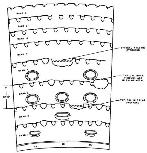
Missing Metal and Burn-Through.— Inspect for
the loss of metal at the panel overhang and the area
between dimples (fig. 2-25). Bum-through of the liners
is not common. What is common are the bluish-black
slag areas that show roughness and appear to be
oxidized. Inspect these areas carefully for T cracks
because they will propagate and open up.
Figure 2-25.—Inner/outer liner burns and missing metal.
2-19