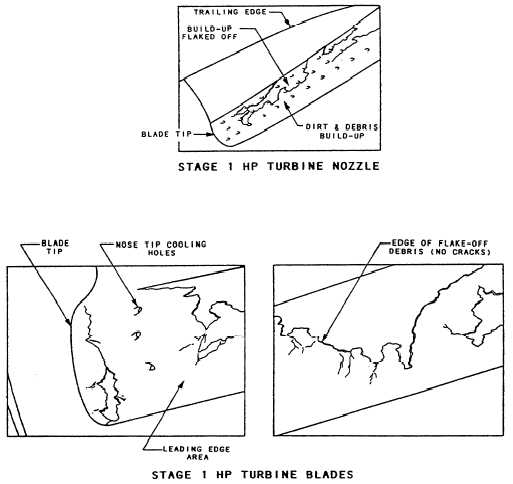
Figure 2-26.—HP turbine blade flaking and buildup.
Record the magnitude and span location relative to the
number of gill holes spanned. Estimate the out of
contour as percent of the leading edge frontal area width
or relative to the lateral spanning of the leading edge
cooling hole rows.
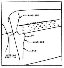
Blade Tip Nibbling.— The HP turbine rotor stage
1 blade tip nibbling is associated with hot running
engines. Momentary overtemperature operation (such
as experienced during compressor stalls) has exhibited
this type of deterioration. This area of the blade is above
the tip cap and located about two-thirds of the chord aft
from the leading edge. Figure 2-27 shows a typical
“nibbled tip” as a result of a severe stall.
Blade Leading Edge Impact Damage.— Figures
2-28 and 2-29 show an impacted and distorted leading
edge of a stage 1 HP turbine rotor blade. (Note the
cracking condition leading from the impact area into the
airfoil surface.) The critical part of this type of damage
is the axial or chord wire cracking. If this cracking
progresses from the impacted damaged area into the
Figure 2-27.—HP turbine blade tip nibbling.
convex or concave airfoil surface, the damage can be
severe.
HP Turbine Blade Coating Failure.— The HP
turbine protective coating is the key factor in the service
2-22