
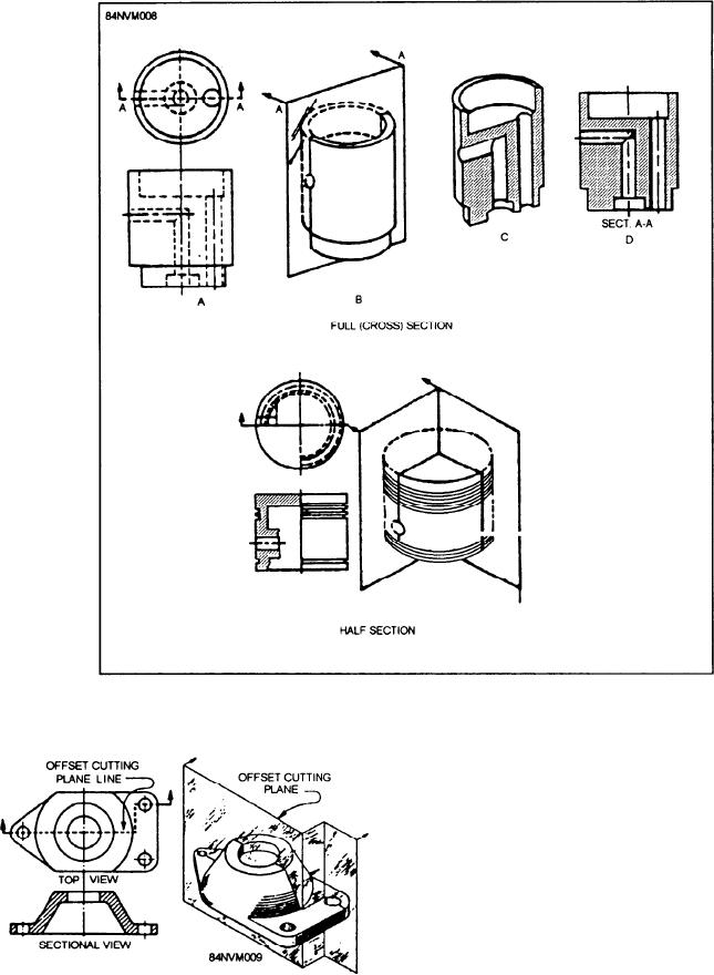
Figure 13-8.--Full- and half-sectional views.
PHANTOM VIEW.--Phantom views are used
to indicate the alternate position of parts of the item
drawn. It may also show repeated detail or the
relative position of an absent part. Figure 13-10
shows a phantom view of a part in the alternate
position. Notice the type of line (the part to the left
of the figure is made up of one long line and two short
dashes) used to represent the item in its original
position.
EXPLODED VIEWS.--The exploded view is
used to show relative location of parts; it is
particularly helpful in assembling complex
Figure 13-9.--Offset section.
objects. Notice how the parts are spread out in a
an offset section view. Notice the different line used to
line to show clearly each part's relationship to the
show the cutting view.
other parts, as shown in figure 13-11.
13-9