
The pipe end in which the cup is to be made must
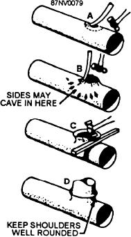
Anneal the area of the pipe that is to be formed.
Then, while the metal is still red hot, work the edge up
be annealed before the work is begun and annealed
with a raising bar, as shown in view A of figure 16-40.
frequently as it is worked. To form the cup, lay the
The sides may tend to cave in, as shown in view B. They
annealed pipe on a grooved wooden block. Insert a
can be bumped out with a bumping ball.
round steel bar in the pipe. The outside diameter of the
bar should be about 0.003 inch greater than the outside
Shape the cup by the method shown in view C of
diameter of the inner pipe. Hold the bar firmly against
figure 16-40 until it fits snugly around the end of the
the pipe, with the inserted end of the bar exactly at the
branch. Then peen the end of the branch to fit the
contour of the cup. Flux and braze the joint. If necessary,
place where the cup is to begin. Then hammer the steel
peen the inside to ensure a smooth surface that will not
bar. Revolve the pipe slightly and hammer the steel bar
interfere with the flow of fluid in the system.
again. Continue to revolve the pipe and hammer the
steel bar until the cup is formed. Stop whenever
necessary to anneal the pipe end.
MAINTENANCE AND REPAIR
OF VALVES
When the cup has been formed so that the inside
pipe will fit into the cup, flare the end of the cup slightly.
Preventive maintenance is the best way to extend
Then anneal and clean the cupped end of the pipe.
the service life of valves and fittings. As soon as you
Immediately after cleaning, apply flux evenly to each
observe a leak, determine the cause, then apply the
joint surface to be brazed.
proper corrective maintenance. Maintenance may be as
simple as tightening a packing nut or gland. A leaking
After the two pipes have been fitted together, caulk
flange joint may need only to have the bolts tightened
the bottom edge of the cup tight against the inside pipe
or to have a new gasket or O-ring inserted. Dirt and
(fig. 16-39). Then braze the joint.
scale, if allowed to collect, can ultimately cause
leakage. Loose hangers permit sections of a line to sag,
Making a Cup Branch
and the weight of the pipe and the fluids in these sagging
sections may strain joints to the point of leakage.
You will often use a cup branch to fit a branch line
Always refer to the applicable PMS procedures and the
into a main line. One procedure for making a cup branch
Navy Standard Valve Technical Manual. When making
is shown in figure 16-40. First, drill a small hole in the
valve repairs on more sophisticated valve types, you
main line pipe at the center of the intersection.
should refer to the manufacturer's technical manual.
Whenever you install a valve, be sure you know the
function the valve is to perform; that is, whether it must
prevent back flow, begin flow, stop flow, regulate flow,
or regulate pressure. Inspect the valve body for
information that is stamped on it by the manufacturer:
type of system (oil, water, or gas), operating pressure,
direction of flow, and other information.
You should also know the operating characteristics
of the valve, the type of metal from which it is made,
and the type of end connection it has. Operating
characteristics and the type of material are factors that
affect the length and kind of service that a valve will
give. End connections indicate whether or not a
particular valve is suited for installation in the system.
Valves should be installed in accessible places and
with enough headroom to allow for full operation.
Install valves with the stem pointing upward, if
possible. A stem position between straight up and
horizontal is acceptable, but avoid the inverted position
(stem pointing downward). If the valve is installed with
Figure 16-40.--Steps in making a cup branch.
the stem pointed downward, sediments will collect in
16-33