
To find the amount of depth increase, set up the
triangle shown in figure 14-26, view B. In this triangle,
side X is equal to the root radius multiplied by the cosine
of the circular pitch angle
Side X = Root radius Cos
To find the depth increase, subtract side X from the
root radius: Depth increase = Root radius - Side X.
The cutting procedure is as follows:
1. Center the cutter on the gear blank.
2. Offset the calculated setover away from the
column. The direction of the offset is optional.
3. Move the cutter down to the whole depth of the
tooth, plus the calculated amount of depth increase in
increments to suit the machine and the setup. Cut the
teeth all the way around the blank until one side of the
tooth is complete.
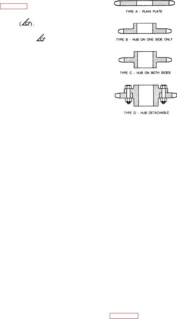
Figure 14-27.--Types of sprockets.
4. Move the cutter back to the center line and offset
toward the column face the calculated amount of
self-centering action under load, even when there is
setover. Cut to the full depth of the tooth plus the amount
backlash between mating members.
of depth increase. At this time, you are ready to debur
your stub tooth gear.
These splines or multiple keys are similar in form
to internal and external involute gears. The general
practice is to form external splines by hobbing, rolling,
SPLINES
or on a gear shaper, and internal splines either by
A splined shaft has a series of parallel keys formed
broaching or on a vertical shaper. The internal spline is
integrally with the shaft. These mate with
held to basic dimensions, and the external spline is
corresponding grooves cut in a hub or fitting. This is in
varied to control the fit. Involute splines have maximum
contrast to a hub or fitting with a series of keys or
strength at the base; they can be accurately spaced and
feathers fitted into slots cut into the shaft. This latter
are self-centering. This equalizes the bearing and
construction weakens the shaft to a considerable degree
stresses, and they can be measured and fitted accurately.
because of the slots cut into it and, as a consequence,
The American National Standard covers involute
reduces its torque-transmitting capacity.
splines with tooth numbers ranging from 6 to 60 with a
Splined shafts are generally used in three types of
30 or 37.5-degree pressure angle, and from 6 to 100 with
applications: (1) to couple shafts when relatively heavy
a 45-degree pressure angle. When you select the number
torques are to be transmitted without slippage; (2) to
of teeth for a given spline application, remember these
transmit power to sliding or permanently fixed gears,
points: (1) There are no advantages in using odd
pulleys, and other rotating members; and (3) to attach
numbers of teeth. (2) The diameters of splines with odd
parts that may require removal for indexing or a change
tooth numbers, particularly internal splines, are
in angular position.
troublesome to measure with pins since no two spaces
are diametrically opposite each other.
Splines with straight-sided teeth have been used in
many applications. However, the use of splines with
involute teeth has increased steadily. Splines with
SPROCKETS
involute teeth are becoming more popular for these
reasons: (1) involute spline couplings have greater
Webster's dictionary defines a sprocket wheel as "a
torque-transmitting capacity than any other type;
wheel with cogs or sprockets to engage with the links
(2) they can be produced with the same techniques and
of a chain." Most sprockets are one of the four types
equipment used to cut gears; and (3) they have a
shown in figure 14-27. The following material briefly
14-29