
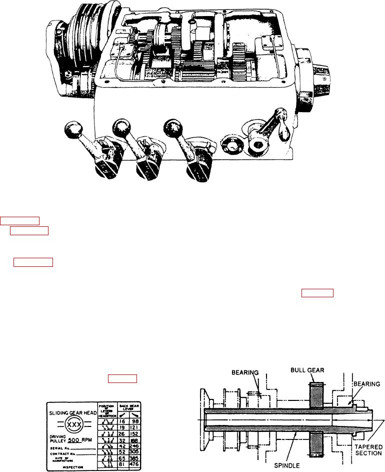
Figure 6-3.--Sliding gear-type headstock
Figure 6-4 shows this plate for the geared headstock
The headstock casing is filled with oil to lubricate
the gears and the shifting mechanism it contains.
in figure 6-3. Always stop the lathe when you shift
Parts not immersed in the oil are lubricated by either
gears to avoid damaging the gear teeth.
the splash produced by the revolving gears or by an
oil pump. Be sure to keep the oil to the oil level
Figure 6-3 shows the interior of a typical geared
indicated on the oil gauge.
headstock that has 16 different spindle speeds. The
driving pulley at the left is driven at a constant speed
by a motor located under the headstock. Various
The headstock spindle (fig. 6-5) is the main
combinations of gears in the headstock transmit the
rotating element of the lathe and is directly connected
power from the drive shaft to the spindle through an
to the work, which revolves with it. The spindle is
intermediate shaft. Use the speed-change levers to
supported in bearings at each end of the headstock
shift the sliding gears on the drive and intermediate
through which it projects. The section of the spindle
shafts to line up the gears in different combinations.
This produces the gear ratios you need to obtain the
various spindle speeds. Note that the back gear lever
has high and low speed positions for each
combination of the other gears (fig. 6-4).
Figure 6-5.--Cross section of a headstock spindle.
Figure 6-4.--Speed index plate.
6-4