
There must be lip clearance behind the entire
length of the cutting edge lip that extends from the
margin of the drill to the chisel edge. This means that
there must be "relief' behind the cutting lip along its
entire length.
W h e n you grind lip clearance, use the
lip-clearance angle and the chisel-edge angle (shown
in figs. 5-30, view C and 5-31, view C) as your guide
to the amount of clearance you have ground into the
drill behind the cutting lip along its entire length. The
greater these angles are, the more clearance there will
be behind their respective ends of the cutting lip. Too
much lip clearance occurs when both the lip-clearance
angle and the chisel-edge angle exceed their top
limits. This weakens the cutting edge or lip by
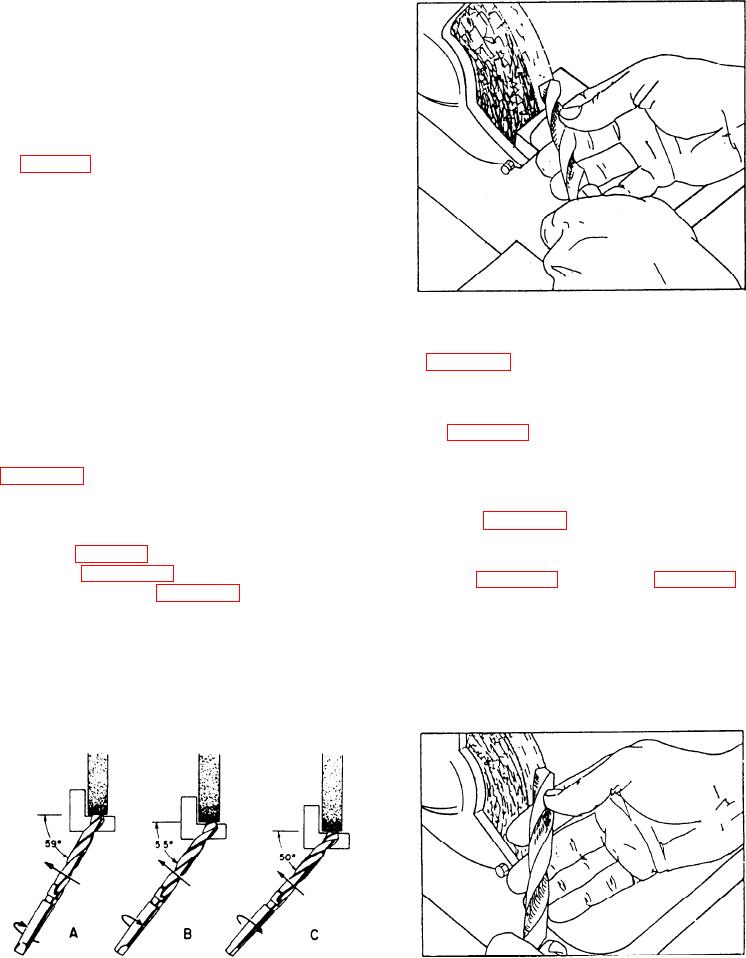
Figure 5-35.--Grinding a twist drill with a grinder (initial
removing too much metal directly behind it. Too little
position.
or no lip clearance prevents the cutting edge from
producing a chip, and the drill bit will not drill a hole.
Figure 5-34 shows the motion to the left in three
views as the angle between the face of the wheel and
To sharpen a twist drill, first ensure the grinder is
the drill decreases from about 59 to about 50.
ready. If necessary, dress the face of the wheel and
In figure 5-34, the rotation arrows in views A, B,
adjust the toolrest. Start the grinder, let it come up to
and C show the clockwise motion. The change in the
speed, and begin. Hold the twist drill as shown in
position of the cutting lip and tang also shows
figure 5-34, view A, which is a top view of the first
rotation.
step in grinding a drill. In the first step, be sure the
axis of the drill makes an angle of about 59 (half of
Because figure 5-34 is a top view, the downward
the drill-point angle) with the face of the wheel as
motion is not noticeable. However all three motions
shown in fig. 5-34, view A. Hold the cutting lip
are apparent when you compare the final position of
horizontal. Figure 5-35 is a side view of the same
the drill in figure 5-36 to the view in figure 5-35. All
drill position shown in figure 5-34, view A.
three motions taking place at the same time combine
to produce the requirements mentioned earlier in this
The actual grinding of the drill point consists of
section: (1) equal and correctly sized drill-point
three definite motions of the shank of the drill while
angles, (2) equal-length cutting lengths, (3) correct
you hold the point lightly against the rotating wheel.
clearance behind the cutting lips, and (4) correct
These three motions are (1) to the left, (2) clockwise
rotation, and (3) downward.
Figure 5-34.--Three steps for grinding a twist drill with a
Figure 5-36.--Grinding a twist drill with a grinder (final
grinder.
position.
5-22