
TM 55-2815-574-24
0032
INSTALLATION - Continued
25.
Remove twine securing two red battery power leads outboard.
26.
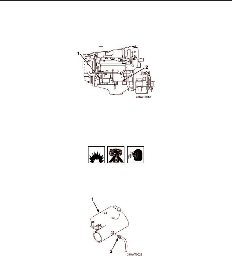
Route two red battery power leads to engine and attach to starter solenoid (Figure 30, Item 2) and alternator
(Figure 30, Item 1) respectively.
Figure 30. Starter Solenoid and Alternator Installation.
27.
Install new tiedown straps on two red battery power leads as required and remove tags.
28.
Remove twine securing cold pack starting supply line (Figure 31, Item 2) outboard.
WARNING
Hazardous fumes may be present. Wear protective clothing and goggles while handling.
Failure to comply may result in personnel injury or death.
29.
Install cold pack starting supply line (Figure 31, Item 2) on starboard side of air inlet housing
(Figure 31, Item 1) and tighten fitting on cold pack starting supply line (Figure 31, Item 2).
Figure 31. Air Inlet Housing Installation.
30.
Position fire suppression trip mechanism cross-module bracket (Figure 32, Item 11) over engine.
31.
Install four bolts (Figure 32, Item 10), flat washers (Figure 32, Item 9), and nuts (Figure 32, Item 3) to secure
the cross-module bracket (Figure 32, Item 11) to propulsion module longitudinal frame.

