
TM 55-2815-574-24
0032
INSTALLATION - Continued
19.
Remove twine securing two supply lines (Figure 28, Items 1 and 2) to engine.
20.
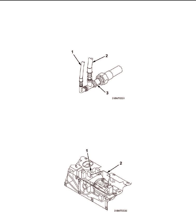
Install fuel pump supply line (Figure 28, Item 2) on fuel supply line check valve (Figure 28, Item 3) and
tighten fitting on fuel pump supply line (Figure 28, Item 2).
21.
Install fuel primer pump supply line (Figure 28, Item 1) on fuel supply line check valve (Figure 28, Item 3)
and tighten fitting on fuel primer pump supply line (Figure 28, Item 1).
Figure 28. Fuel Supply Check Valve Installation.
22.
Remove twine securing main engine electrical wire bundle (Figure 29, Item 2) on top of engine.
23.
Route main engine electrical wire bundle (Figure 29, Item 2) from engine junction box A4 (Figure 29, Item 1)
to engine, securing bundle with new tiedown straps as required.
24.
Connect main engine electrical wire bundle (Figure 29, Item 2) to engine junction box A4 (Figure 29, Item 1)
and remove tags.
Figure 29. Engine Junction Box Installation.